
A02YYUW Waterproof Ultrasonic Distance Sensor
The A02YYUW is a waterproof ultrasonic distance sensor ideal for outdoor and industrial applications. With a measuring range of up to 4.5 meters and a durable build, it is perfect for detecting objects in harsh conditions. It operates using a UART interface and is compatible with microcontrollers like Arduino and ESP32.

A02YYUW pinout
The A02YYUW pinout includes four pins: VCC (power), GND (ground), TX (UART transmit), and RX (UART receive). The sensor communicates distance data via UART protocol.
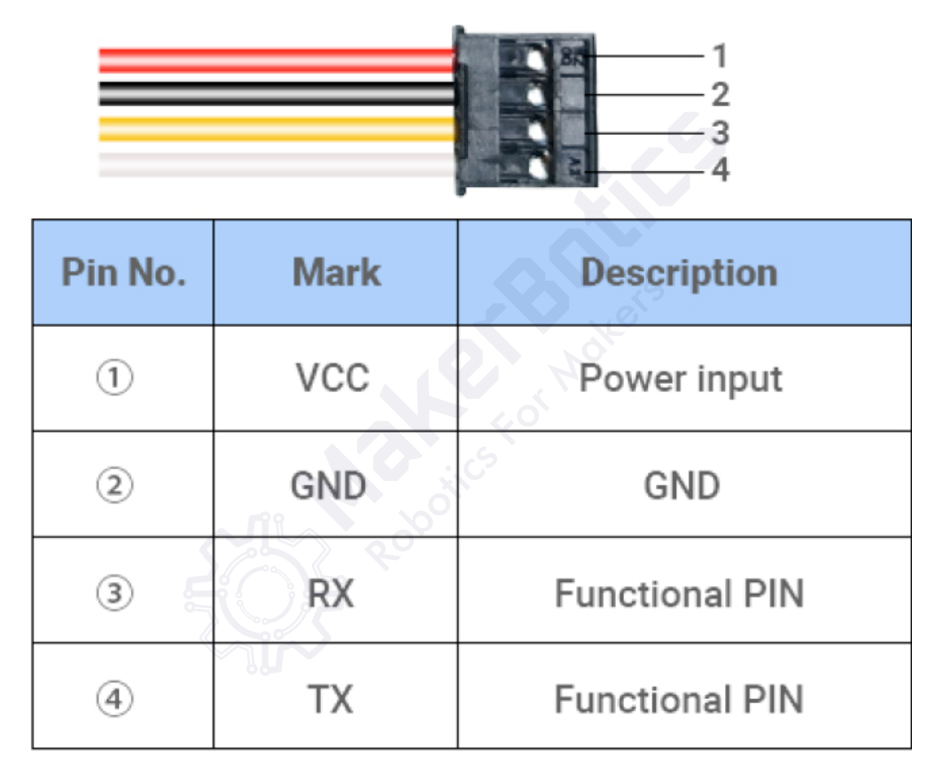
| Pin | Type | Description | Notes |
|---|---|---|---|
| VCC | Power | Power supply input (3.3V to 5.5V) | Recommended 5V for optimal performance |
| GND | Ground | Ground connection | Connect to common ground |
| TX | UART TX | UART Transmit Data (sensor output) | Connects to microcontroller RX pin |
| RX | UART RX | UART Receive Data (sensor input) | Connects to microcontroller TX pin (optional) |
Waterproof ultrasonic distance sensor with IP67 rating
Measurement range: 3 cm to 450 cm
Resolution: 1 mm
Accuracy: ±1 cm
UART baud rate: 9600 bps (8N1: 8 data bits, no parity, 1 stop bit)
Operating voltage: 3.3V to 5.5V (5V recommended)
Operating temperature: -15°C to +70°C
Waterproof and dustproof (IP67) for outdoor use
Wiring the A02YYUW to ESP32
Connect the A02YYUW to your ESP32 via UART. The sensor transmits distance readings automatically via the TX pin. Power the sensor with 5V for best performance, though 3.3V operation is supported.
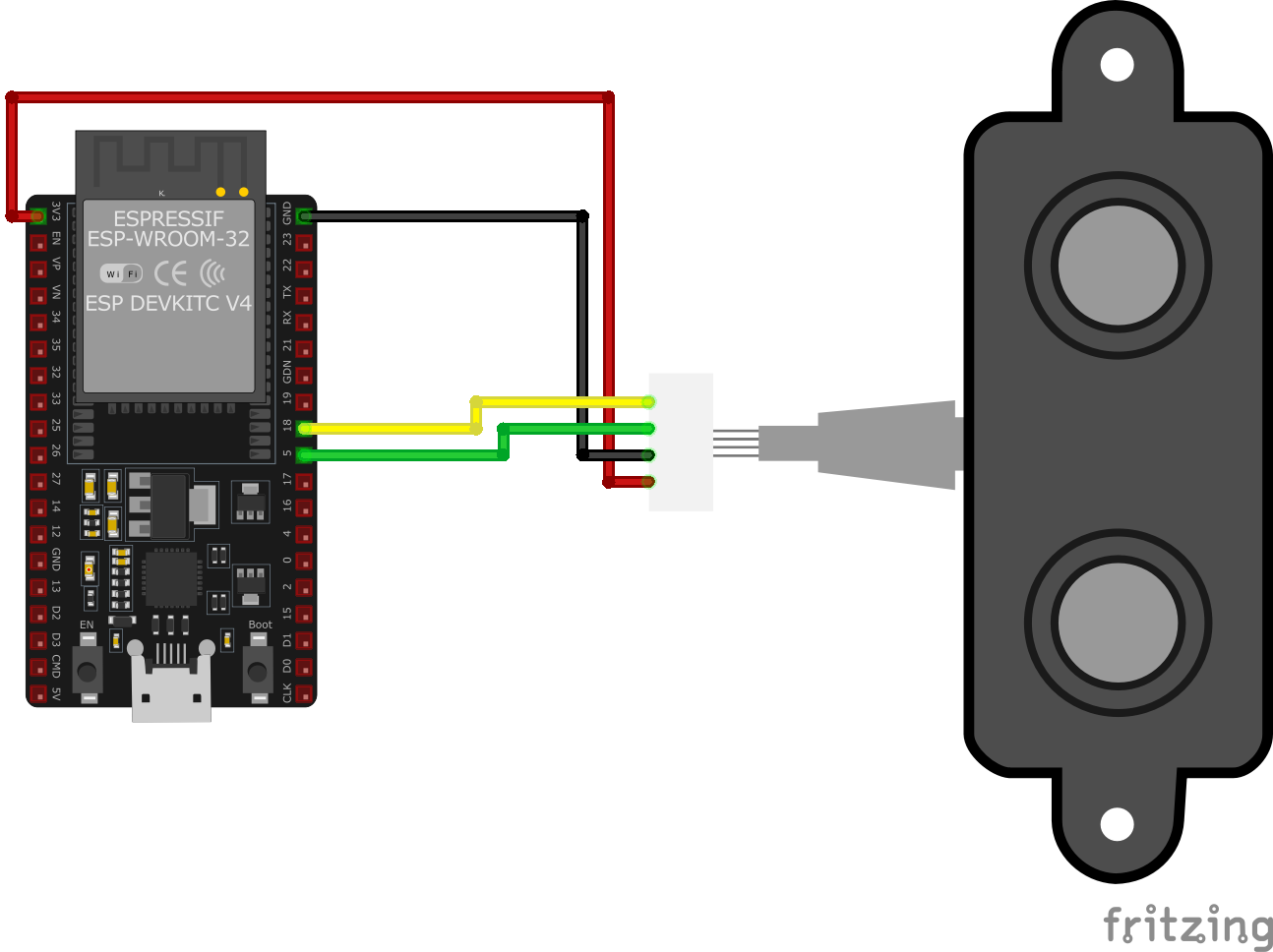
| A02YYUW pin | ESP32 pin | Purpose |
|---|---|---|
| VCC | 5V or 3.3V | Power supply (5V recommended) |
| GND | GND | Ground connection |
| TX | GPIO16 (RX2) | Sensor TX to ESP32 RX (distance data) |
| RX | GPIO17 (TX2) | Sensor RX to ESP32 TX (optional) · optional |
UART communication: 9600 baud, 8 data bits, no parity, 1 stop bit
Sensor transmits distance data automatically every 100-300ms
Data format: 4-byte frame (0xFF start byte + 2 distance bytes + checksum)
RX pin is optional - sensor works in output-only mode
5V power recommended for maximum range and accuracy
IP67 waterproof rating - suitable for outdoor installations
Avoid placing sensor near other ultrasonic devices (interference)
Mount sensor perpendicular to target surface for best accuracy
Soft or angled surfaces may affect accuracy
Temperature changes affect speed of sound - consider compensation
A02YYUW code examples
#include <Arduino.h>

// Define ESP32 hardware serial port for the A02YYUW sensor
#define A02YYUW_TX 18  // ESP32 TX connected to Sensor RX
#define A02YYUW_RX 5   // ESP32 RX connected to Sensor TX

// Initialize hardware serial for A02YYUW
HardwareSerial mySerial(2);

void setup() {
    Serial.begin(115200);  // Initialize Serial Monitor
    mySerial.begin(9600, SERIAL_8N1, A02YYUW_RX, A02YYUW_TX);  // Initialize UART2
    Serial.println("A02YYUW Distance Sensor Example");
}

void loop() {
    if (mySerial.available() >= 4) {
        uint8_t data[4];
        for (int i = 0; i < 4; i++) {
            data[i] = mySerial.read();
        }

        if (data[0] == 0xFF) {  // Check packet start byte
            int sum = (data[0] + data[1] + data[2]) & 0xFF;
            if (sum == data[3]) {  // Validate checksum
                int distance = (data[1] << 8) + data[2];  // Calculate distance
                if (distance > 30) {  // Ensure valid reading
                    Serial.print("Distance: ");
                    Serial.print(distance / 10.0);
                    Serial.println(" cm");
                } else {
                    Serial.println("Below the lower limit");
                }
            } else {
                Serial.println("Checksum error");
            }
        }
    }
    delay(100);
}
This Arduino sketch interfaces with the A02YYUW ultrasonic distance sensor using ESP32’s hardware serial (UART2) for stable communication.
Hardware Serial on ESP32
ESP32 has multiple hardware UART ports, eliminating the need for SoftwareSerial. This sketch uses UART2 (Serial2):
- TX (GPIO18) → Sensor RX
- RX (GPIO5) → Sensor TX
- Baud rate: 9600
Code Breakdown
- Initialize UART2 with
mySerial.begin(9600, SERIAL_8N1, A02YYUW_RX, A02YYUW_TX); - Read sensor data (4-byte packets).
- Validate checksum for data integrity.
- Convert distance to cm and print it to the Serial Monitor.
- Error handling for checksum failures and out-of-range readings.
This setup ensures reliable distance measurement without using SoftwareSerial.
#include <stdio.h>
#include "driver/uart.h"
#include "esp_log.h"
#include "freertos/FreeRTOS.h"
#include "freertos/task.h"

#define RXD_PIN 16
#define TXD_PIN 17
#define UART_NUM UART_NUM_1
#define UART_BUFFER_SIZE (1024 * 2)
#define UART_TIMEOUT_MS 20

static const char *TAG = "UART_SENSOR";

void init_uart(void) {
    // Configure UART parameters
    const uart_config_t uart_config = {
        .baud_rate = 9600,
        .data_bits = UART_DATA_8_BITS,
        .parity = UART_PARITY_DISABLE,
        .stop_bits = UART_STOP_BITS_1,
        .flow_ctrl = UART_HW_FLOWCTRL_DISABLE
    };

    // Apply UART configuration
    ESP_ERROR_CHECK(uart_param_config(UART_NUM, &uart_config));
    ESP_ERROR_CHECK(uart_set_pin(UART_NUM, TXD_PIN, RXD_PIN, UART_PIN_NO_CHANGE, UART_PIN_NO_CHANGE));

    // Install UART driver with RX buffer and a small TX buffer
    ESP_ERROR_CHECK(uart_driver_install(UART_NUM, UART_BUFFER_SIZE, 512, 0, NULL, 0));

    // Set UART mode explicitly
    ESP_ERROR_CHECK(uart_set_mode(UART_NUM, UART_MODE_UART));
}

void uart_task(void *pvParameters) {
    uint8_t data[4];

    while (1) {
        // Read 4 bytes from UART
        int len = uart_read_bytes(UART_NUM, data, 4, pdMS_TO_TICKS(UART_TIMEOUT_MS));

        if (len == 4 && data[0] == 0xFF) {
            // Calculate checksum
            int sum = (data[0] + data[1] + data[2]) & 0xFF;
            if (sum == data[3]) {
                // Convert distance to centimeters
                int distance = (data[1] << 8) | data[2];

                if (distance > 30) {
                    ESP_LOGI(TAG, "Distance: %.2f cm", distance / 10.0);
                } else {
                    ESP_LOGW(TAG, "Below the lower limit");
                }
            } else {
                ESP_LOGE(TAG, "Checksum error (Received: 0x%02X, Expected: 0x%02X)", data[3], sum);
            }
        } else if (len > 0) {
            ESP_LOGW(TAG, "Invalid data received");
        }

        vTaskDelay(pdMS_TO_TICKS(100));
    }
}

void app_main(void) {
    init_uart();
    xTaskCreate(uart_task, "UART Task", 4096, NULL, 5, NULL);
}
This ESP-IDF code interfaces with the A02YYUW ultrasonic distance sensor using UART1 on the ESP32.
UART Configuration
- TX (GPIO17) → Sensor RX, RX (GPIO16) → Sensor TX
- Baud rate: 9600, 8N1 format
- RX buffer: 2048 bytes
Code Breakdown
- Initialize UART with
init_uart(), setting up UART parameters and driver. - Read Sensor Data in
uart_task(), processing 4-byte packets. - Validate Data by checking the header (0xFF) and checksum.
- Convert Distance from mm to cm and print it to the Serial Monitor.
A 100 ms delay ensures stable readings.
uart:
  rx_pin: GPIO16  # sensor TX -> GPIO16 (RX2)
  tx_pin: GPIO17  # sensor RX -> GPIO17 (TX2)
  baud_rate: 9600

sensor:
  - platform: a02yyuw
    name: "A02YYUW Distance"
The a02yyuw platform reads the sensor's UART frames directly - wire the sensor's TX to GPIO16 and RX to GPIO17 (UART2) as shown above. The sensor pushes readings on its own cadence, so the platform takes no update_interval; ESPHome publishes each valid distance in millimeters as it arrives.
[env:esp32dev]
platform = espressif32
board = esp32dev
framework = arduino
monitor_speed = 115200#include <Arduino.h>
// Define ESP32 hardware serial port for the A02YYUW sensor
#define A02YYUW_TX 18 // ESP32 TX connected to Sensor RX
#define A02YYUW_RX 5 // ESP32 RX connected to Sensor TX
// Initialize hardware serial for A02YYUW
HardwareSerial mySerial(2);
void setup() {
Serial.begin(115200); // Initialize Serial Monitor
mySerial.begin(9600, SERIAL_8N1, A02YYUW_RX, A02YYUW_TX); // Initialize UART2
Serial.println("A02YYUW Distance Sensor Example");
}
void loop() {
if (mySerial.available() >= 4) {
uint8_t data[4];
for (int i = 0; i < 4; i++) {
data[i] = mySerial.read();
}
if (data[0] == 0xFF) { // Check packet start byte
int sum = (data[0] + data[1] + data[2]) & 0xFF;
if (sum == data[3]) { // Validate checksum
int distance = (data[1] << 8) + data[2]; // Calculate distance
if (distance > 30) { // Ensure valid reading
Serial.print("Distance: ");
Serial.print(distance / 10.0);
Serial.println(" cm");
} else {
Serial.println("Below the lower limit");
}
} else {
Serial.println("Checksum error");
}
}
}
delay(100);
}This PlatformIO example reads the A02YYUW over the ESP32's second hardware UART (UART2: sensor TX to GPIO16, RX to GPIO17) - the AVR-style SoftwareSerial library is neither available nor needed on the ESP32. Each 4-byte frame starts with 0xFF; the sketch validates the checksum and prints the distance (frames report millimeters, shown as centimeters).
from machine import UART
from time import sleep

# Configure UART
uart = UART(2, baudrate=9600, tx=5, rx=18)

def read_distance():
    if uart.any() >= 4:
        data = uart.read(4)
        if data[0] == 0xFF:
            checksum = (data[0] + data[1] + data[2]) & 0xFF
            if checksum == data[3]:
                distance = (data[1] << 8) | data[2]
                if distance > 30:
                    return distance / 10.0
                else:
                    return "Below the lower limit"
            else:
                return "Checksum error"
    return None

print("A02YYUW Distance Sensor Example")

while True:
    result = read_distance()
    if result:
        print(f"Distance: {result} cm")
    sleep(0.1)
This MicroPython script uses UART to communicate with the A02YYUW sensor. The UART is configured on TX pin GPIO17 and RX pin GPIO16 at a baud rate of 9600. The read_distance() function reads 4 bytes of data from the UART buffer, validates the header and checksum, and calculates the distance in millimeters. The result is converted to centimeters and returned. The main loop continuously calls this function every 100 ms to print the distance to the console. If the sensor detects an issue, such as a checksum error or a distance below the minimum threshold, appropriate messages are displayed.
A02YYUW specifications
About the A02YYUW
The A02YYUW is DFRobot’s SEN0311, a waterproof ultrasonic distance sensor built to skip the trigger/echo dance entirely: it talks plain UART at a fixed 9600 baud, pushing a distance reading on its own roughly every 100 ms with no trigger pulse needed from the host. Each frame is four bytes - a 0xFF header, two bytes of distance in millimeters, and a checksum - simple enough to parse by hand and free of the microsecond-precision timing a HC-SR04’s pulseIn() loop depends on. The IP67 housing and 3.3-5V supply range mean it can sit outside or in a wet enclosure and run directly off an ESP32’s 3.3V rail without a voltage divider on any pin, unlike the HC-SR04’s 5V echo output.
Per DFRobot’s own specification, the working range is 3 to 450 cm with a blind zone of only about 3 cm - noticeably tighter than the roughly 20-25 cm dead zone on the waterproof JSN-SR04T, a real advantage for sensing something close to the sensor face, like a near-full tank or a nearby obstacle.
At close to 16 dollars it costs several times more than either of those alternatives, so the premium buys two specific things: IP67 waterproofing and a simpler UART interface. If a project stays indoors and dry, the plain HC-SR04 does the same job for a fraction of the price; if it needs to survive outdoors but budget matters more than blind zone, the JSN-SR04T is the cheaper waterproof option, at the cost of a wider dead zone and a return to trigger/echo timing (plus its own voltage divider).
A02YYUW troubleshooting
Sensor Returns Constant or Erroneous Readings
›
Issue: The A02YYUW ultrasonic sensor provides constant or incorrect distance measurements, regardless of the actual distance to the target.
Possible causes include incorrect wiring, insufficient power supply, or improper sensor configuration.
Solution: Ensure that the sensor is connected to a stable 5V power source, as it requires 5V for proper operation. Verify that the sensor's TX (transmit) and RX (receive) lines are correctly connected to the corresponding RX and TX pins on the microcontroller, respectively. Confirm that the baud rate for serial communication is set to 9600 bps, as required by the sensor.
Inconsistent or Fluctuating Distance Measurements
›
Issue: The sensor outputs distance readings that vary significantly, even when the target distance remains constant.
Possible causes include environmental factors such as temperature variations, soft or angled target surfaces, or electrical noise.
Solution: Position the sensor perpendicular to a hard, flat target surface to ensure accurate reflections. Be aware that temperature changes can affect the speed of sound; consider implementing temperature compensation if precise measurements are required. Implement averaging of multiple readings in your code to mitigate occasional erroneous data.
Sensor Not Detected or Unresponsive
›
Issue: The microcontroller fails to detect the A02YYUW sensor, or the sensor does not respond to trigger signals.
Possible causes include incorrect pin assignments in the code, lack of proper initialization, or defective sensor module.
Solution: Double-check the pin assignments in your code to ensure they match the physical connections. Confirm that the sensor is properly initialized in the setup section of your code. If the issue persists, test the sensor with a known working setup or replace it to rule out hardware failure.
Interference from Environmental Factors
›
Issue: External factors cause the sensor to produce unreliable readings.
Possible causes include high ambient noise levels, temperature variations, or obstacles in the sensor's field of view.
Solution: Operate the sensor in a controlled environment to minimize acoustic and electrical noise. Be aware that temperature changes can affect the speed of sound; consider implementing temperature compensation if precise measurements are required. Ensure that there are no unintended obstacles within the sensor's detection range that could cause false readings.
Where to buy the A02YYUW

Resources
Similar sensors


