
GY-530 VL53L0X Time-of-Flight Sensor
The GY-530 is a breakout board for the VL53L0X Time-of-Flight (ToF) sensor from STMicroelectronics. It uses FlightSense technology to measure distances up to 2 meters with 1mm resolution and includes onboard level shifting and voltage regulation, making it compatible with 3.3V and 5V microcontrollers.

GY-530 pinout
The GY-530 breakout board has 6 pins for the VL53L0X Time-of-Flight sensor with onboard regulation and level shifting.
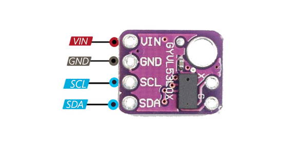
| Pin | Type | Description | Notes |
|---|---|---|---|
| VIN | Power | Power input (2.6V-5.5V). Wide voltage range with onboard regulator. | Use 3.3V or 5V depending on microcontroller. |
| GND | Power | Ground connection. Connect to system ground. | |
| SCL | I2C | I²C clock line (level-shifted to VIN voltage). | Connect to ESP32 GPIO 22. Level shifters included. |
| SDA | I2C | I²C data line (level-shifted to VIN voltage). | Connect to ESP32 GPIO 21. Level shifters included. |
| XSHUT | Control | Shutdown pin (active low). Pull low to disable sensor. | Optional - used for software reset or multi-sensor setups. |
| VDD | Power | 2.8V output from onboard regulator. Can power external 2.8V devices. | Max 10mA output. Can also be used as input if VIN disconnected. |
Based on VL53L0X Time-of-Flight sensor
Range: 3cm to 200cm (2 meters) with 1mm resolution
I²C address: 0x29 (default, can be changed in software)
Class 1 laser (940nm, eye-safe)
Onboard 2.8V regulator and I²C level shifters
Available in blue and purple PCBs (functionally identical)
Wiring the GY-530 to ESP32
To interface the GY-530 with an ESP32 via I²C, connect VIN to 3.3V or 5V, GND to ground, SDA to GPIO 21, and SCL to GPIO 22.
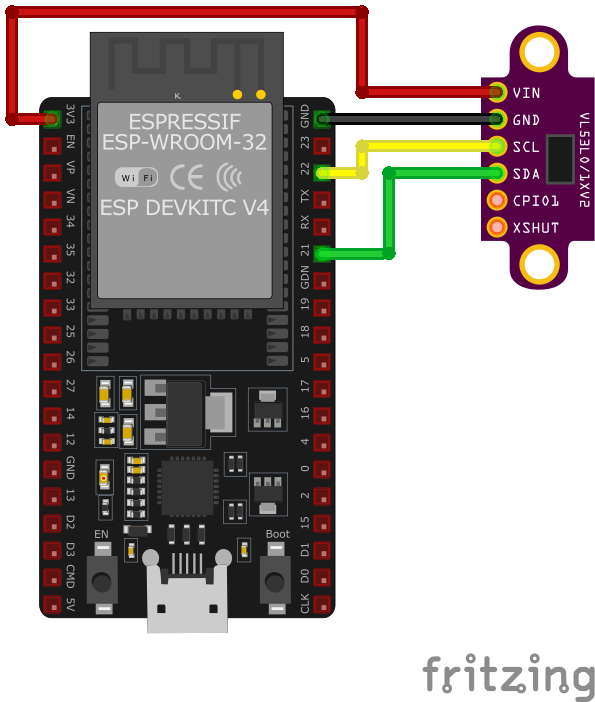
| GY-530 pin | ESP32 pin | Purpose |
|---|---|---|
| VIN | 3.3V or 5V | Power supply. Use 3.3V or 5V (onboard regulator handles both). |
| GND | GND | Ground connection. |
| SDA | GPIO 21 | I²C data line. Level shifters included on board. |
| SCL | GPIO 22 | I²C clock line. Level shifters included on board. |
| XSHUT | Optional GPIO or VIN | Shutdown control. Pull high for normal operation. · optional |
I²C address: 0x29 (default, can be changed via software)
No external pull-up resistors needed - included on breakout board
Onboard level shifters - safe for 3.3V and 5V systems
Use Adafruit_VL53L0X or VL53L0X_rasp library
Range: 30mm to 2000mm (optimal: 50-1200mm)
FOV: 25° (best accuracy with perpendicular surfaces)
For multiple sensors: use XSHUT to set unique I²C addresses
Measurement modes: Single, Continuous, Timed
Accuracy: ±3% at distances > 200mm
GY-530 code examples
#include <Wire.h>
#include <Adafruit_VL53L0X.h>

Adafruit_VL53L0X lox = Adafruit_VL53L0X();

void setup() {
    Serial.begin(115200);
    Wire.begin();

    if (!lox.begin()) {
        Serial.println("Failed to initialize VL53L0X! Check connections.");
        while (1);
    }
    Serial.println("VL53L0X Initialized.");
}

void loop() {
    VL53L0X_RangingMeasurementData_t measure;
    lox.rangingTest(&measure, false);

    if (measure.RangeStatus != 4) { // Status 4 means no object detected
        Serial.print("Distance: ");
        Serial.print(measure.RangeMilliMeter);
        Serial.println(" mm");
    } else {
        Serial.println("Out of range.");
    }

    delay(500);
}
This Arduino code demonstrates how to use the VL53L0X sensor with the Adafruit library. It initializes the sensor using the lox.begin() method. In the loop(), the rangingTest() method measures the distance to an object in millimeters, which is printed to the Serial Monitor every 500 ms. If no object is detected or the object is out of range, a corresponding message is displayed. The I2C protocol facilitates communication with the sensor. The GY-530 is a VL53L0X breakout - everything on the VL53L0X page applies.
// Minimal raw-I2C single-shot ranging for the VL53L0X (address 0x29).
// The chip boots with usable default settings; this reads uncalibrated
// distance directly. For production accuracy, use ST's VL53L0X API.
#include <stdio.h>
#include "freertos/FreeRTOS.h"
#include "freertos/task.h"
#include "driver/i2c.h"
#define I2C_MASTER_SCL_IO 22
#define I2C_MASTER_SDA_IO 21
#define I2C_MASTER_NUM I2C_NUM_0
#define I2C_MASTER_FREQ_HZ 100000
#define VL53L0X_ADDR 0x29
#define REG_SYSRANGE_START 0x00
#define REG_RESULT_INTERRUPT_STATUS 0x13
#define REG_RESULT_RANGE_MM 0x1E // RESULT_RANGE_STATUS + 10
#define REG_SYSTEM_INTERRUPT_CLEAR 0x0B
static esp_err_t wr8(uint8_t reg, uint8_t val) {
uint8_t buf[2] = {reg, val};
return i2c_master_write_to_device(I2C_MASTER_NUM, VL53L0X_ADDR, buf, 2, pdMS_TO_TICKS(1000));
}
static esp_err_t rd(uint8_t reg, uint8_t *data, size_t len) {
return i2c_master_write_read_device(I2C_MASTER_NUM, VL53L0X_ADDR, ®, 1, data, len, pdMS_TO_TICKS(1000));
}
void app_main(void) {
i2c_config_t conf = {
.mode = I2C_MODE_MASTER,
.sda_io_num = I2C_MASTER_SDA_IO,
.scl_io_num = I2C_MASTER_SCL_IO,
.sda_pullup_en = GPIO_PULLUP_ENABLE,
.scl_pullup_en = GPIO_PULLUP_ENABLE,
.master.clk_speed = I2C_MASTER_FREQ_HZ,
};
ESP_ERROR_CHECK(i2c_param_config(I2C_MASTER_NUM, &conf));
ESP_ERROR_CHECK(i2c_driver_install(I2C_MASTER_NUM, conf.mode, 0, 0, 0));
uint8_t model_id = 0;
if (rd(0xC0, &model_id, 1) != ESP_OK || model_id != 0xEE) {
printf("VL53L0X not found (model id 0x%02X) - check wiring\n", model_id);
return;
}
printf("VL53L0X found.\n");
while (1) {
wr8(REG_SYSRANGE_START, 0x01); // Start a single-shot measurement
// Wait for the result (interrupt status bits 0-2 set when ready)
uint8_t status = 0;
for (int i = 0; i < 50; i++) {
rd(REG_RESULT_INTERRUPT_STATUS, &status, 1);
if (status & 0x07) break;
vTaskDelay(pdMS_TO_TICKS(5));
}
if (status & 0x07) {
uint8_t range[2];
rd(REG_RESULT_RANGE_MM, range, 2);
uint16_t distance = (range[0] << 8) | range[1];
if (distance < 8190) {
printf("Distance: %u mm\n", distance);
} else {
printf("Out of range\n");
}
wr8(REG_SYSTEM_INTERRUPT_CLEAR, 0x01);
} else {
printf("Measurement timeout\n");
}
vTaskDelay(pdMS_TO_TICKS(500));
}
}This is a minimal raw-I2C example: the VL53L0X boots with usable default settings, so writing 0x01 to the SYSRANGE_START register triggers a single-shot measurement, the interrupt-status register signals completion, and the 16-bit range in millimeters is read from the result registers (values around 8190 mean out of range). This gives functional but uncalibrated readings - for production accuracy (calibration, long-range/high-accuracy profiles), port ST's official VL53L0X API as an ESP-IDF component. The GY-530 is a VL53L0X breakout - everything on the VL53L0X page applies.
i2c:
  sda: GPIO21
  scl: GPIO22

sensor:
  - platform: vl53l0x
    name: "VL53L0X Distance"
    update_interval: 500ms
This ESPHome configuration uses the vl53l0x platform to interface with the sensor. The sensor’s name, ‘VL53L0X Distance,’ makes it easily identifiable in home automation platforms like Home Assistant. The update_interval of 500 ms ensures frequent updates for applications requiring real-time distance measurements. The GY-530 is a VL53L0X breakout - everything on the VL53L0X page applies.
[env:esp32dev]
platform = espressif32
board = esp32dev
framework = arduino
monitor_speed = 115200
lib_deps =
adafruit/Adafruit_VL53L0X @ ^1.2.4#include <Arduino.h>
#include <Wire.h>
#include <Adafruit_VL53L0X.h>
Adafruit_VL53L0X lox = Adafruit_VL53L0X();
void setup() {
Serial.begin(115200);
Wire.begin();
if (!lox.begin()) {
Serial.println("Failed to initialize VL53L0X! Check connections.");
while (1);
}
Serial.println("VL53L0X Initialized.");
}
void loop() {
VL53L0X_RangingMeasurementData_t measure;
lox.rangingTest(&measure, false);
if (measure.RangeStatus != 4) { // Status 4 means no object detected
Serial.print("Distance: ");
Serial.print(measure.RangeMilliMeter);
Serial.println(" mm");
} else {
Serial.println("Out of range.");
}
delay(500);
}The PlatformIO code uses the Adafruit VL53L0X library to interface with the sensor. After initializing I2C communication with Wire.begin(), the sensor is configured using lox.begin(). The rangingTest() function retrieves distance measurements in millimeters, which are printed to the Serial Monitor every 500 ms. A status check ensures meaningful data is displayed, and the code gracefully handles ‘out of range’ cases. The GY-530 is a VL53L0X breakout - everything on the VL53L0X page applies.
# Requires driver: VL53L0X.py from https://github.com/uceeatz/VL53L0X
# Copy it to the board: mpremote cp VL53L0X.py :
from machine import I2C, Pin
import time
import VL53L0X

# Initialize I2C (SDA=GPIO21, SCL=GPIO22)
i2c = I2C(0, scl=Pin(22), sda=Pin(21))

# Initialize VL53L0X sensor
tof = VL53L0X.VL53L0X(i2c)
tof.start()

while True:
    distance = tof.read()  # Distance in mm
    print("Distance: {} mm".format(distance))
    time.sleep(0.5)
The example uses the uceeatz/VL53L0X MicroPython driver (copy VL53L0X.py to the board). After start() begins ranging, read() returns the distance in millimeters. The sensor sits at address 0x29 on the default I2C pins. The GY-530 is a VL53L0X breakout - everything on the VL53L0X page applies.
About the GY-530
Despite its own product name, the GY-530 is not a distinct sensor - it is one of several breakout-board names built around STMicroelectronics’s VL53L0X Time-of-Flight chip, confirmed by module listings and datasheets that all point back to ST’s own VL53L0X documentation. Same 940 nm laser emitter, same SPAD-array ranging engine, same fixed I2C address of 0x29, same roughly 2-meter best-case range that shrinks well below that against dark or distant targets. What the GY-530 board actually adds is convenience: an onboard 2.8V regulator and I2C level shifter let it accept anywhere from 2.6V to 5.5V on VIN, so it drops onto a 3.3V ESP32 or a 5V board without extra components.
Because it is the identical die under a different silkscreen, every VL53L0X driver - Adafruit’s library, raw ESP-IDF register code, ESPHome’s vl53l0x platform, MicroPython drivers - runs on the GY-530 unmodified. The board itself ships in a couple of PCB colors (commonly blue or purple) that are functionally interchangeable, and it sits at a similar price to the plain VL53L0X module, the VL53L0X V2 revision, and the TOF200C - all the same chip on different boards.
Given that, there is little reason to shop for the “GY-530” name specifically; buy whichever of those boards is cheapest, in stock, or has the pin layout a project needs. The one sensor in this family actually worth paying more for is the longer-range VL53L1X, which reaches roughly twice the VL53L0X’s distance in good lighting.
GY-530 troubleshooting
Sensor Not Detected
›
Issue: GY-530 not showing up on I²C scanner.
Solution: Ensure SDA/SCL are properly connected and powered, and that XSHUT is not held LOW.
Poor Accuracy or Fluctuating Readings
›
Issue: Distance values jump around or seem wrong.
Solution: Check for surface reflectivity issues, increase timing budget, or average multiple readings.
Sensor Keeps Resetting
›
Issue: Unstable readings or sensor dropping off I²C bus.
Solution: Use a stable 3.3V or 5V supply. Avoid floating XSHUT pin - tie it high if unused.
Where to buy the GY-530

Resources
Similar sensors


