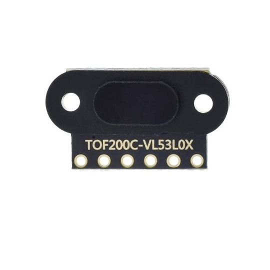
ESP32 VL53L0X Time-of-Flight Distance Sensor
Overview
The VL53L0X is an advanced Time-of-Flight distance sensor offering accurate, laser-based measurements over a range of 30 mm to 2,000 mm. It features low power consumption, compact size, and fast response times, making it ideal for integration into various IoT and robotics applications. The I2C communication protocol simplifies its use with microcontrollers and SBCs like Arduino and Raspberry Pi.
About VL53L0X Time-of-Flight Distance Sensor
The VL53L0X, developed by STMicroelectronics, is a high-precision Time-of-Flight (ToF) sensor that uses laser-based technology to measure distances up to 2 meters with exceptional accuracy. With low power consumption and fast response time, it is ideal for robotics, gesture recognition, and obstacle detection.
⚡ Key Features
- Extended Measurement Range – Accurately detects distances up to 2 meters.
- Laser-Based Time-of-Flight Technology – Ensures fast and precise measurements.
- I²C Communication – Seamlessly integrates with ESP32, Arduino, and other microcontrollers.
- Low Power & Compact Design – Ideal for portable and battery-powered applications.
With its advanced sensing capabilities and efficient performance, the VL53L0X is an excellent choice for embedded systems requiring accurate distance measurement. 🚀
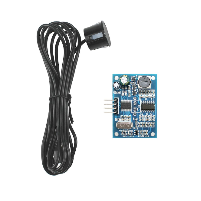
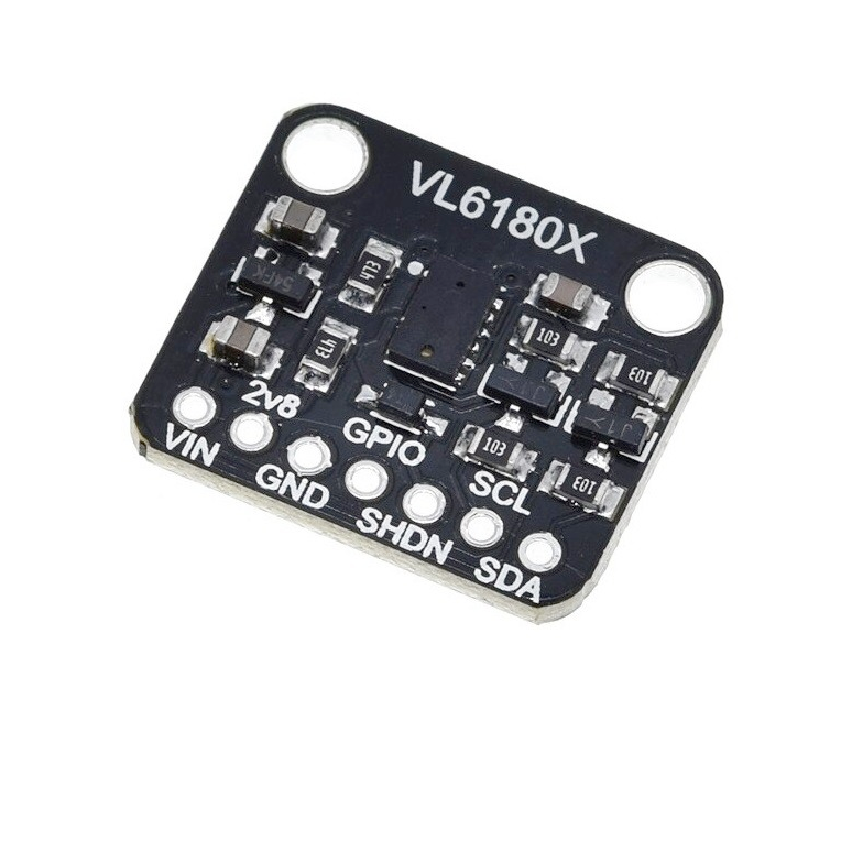
Check Other sensors modules based on VL53L0X Time of Flight Sensor:
Where to Buy

Starting from
5$ per unit



Prices are subject to change. We earn from qualifying purchases as an Amazon Associate.
Technical Specifications
Pinout Configuration
The VCC pin is used to supply power to the sensor, and it typically requires 3.3V or 5V (refer to the datasheet for specific voltage requirements). The GND pin is the ground connection and must be connected to the ground of your ESP32.
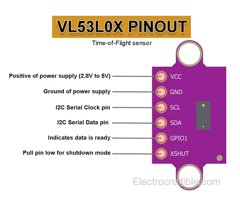
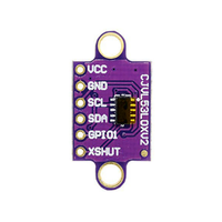
The VL53L0X pinout is as follows:
- VIN: Connect to a 3.3V or 5V power supply.
- GND: Connect to the ground of your microcontroller.
- SCL: I2C clock line, connect to the SCL pin of your microcontroller.
- SDA: I2C data line, connect to the SDA pin of your microcontroller.
- XSHUT: Shutdown pin, can be used to reset the sensor (active low).
- GPIO1: Interrupt pin, optional for advanced configurations.
Wiring with ESP32
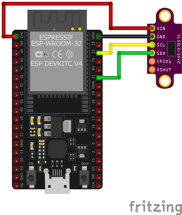
SCL and SDA pins to the respective I2C pins on the microcontroller. The VIN pin should be connected to a 3.3V or 5V power source, and GND to ground. If needed, the XSHUT pin can be used to reset the sensor, and GPIO1 can provide interrupt signals for advanced use cases.Troubleshooting Guide
Common Issues
❌ Sensor Initialization Failure
Issue: The VL53L0X sensor fails to initialize on the ESP32, resulting in errors such as: Failed to boot VL53L0X.
Possible causes include incorrect wiring, insufficient power supply, or improper I2C communication setup.
Solution: Verify that the sensor's SDA and SCL lines are correctly connected to the corresponding I2C pins on the ESP32 (default GPIO21 for SDA and GPIO22 for SCL). Ensure that the sensor is powered within its operating voltage range (2.8V to 5.5V). Use an I2C scanner to confirm the sensor's address (default 0x29) and check for any address conflicts on the bus.
⚠️ Unstable or Incorrect Distance Measurements
Issue: The VL53L0X sensor provides fluctuating or inaccurate distance readings when interfaced with the ESP32.
Possible causes include electrical noise, improper sensor alignment, or interference from ambient light sources.
Solution: Ensure that the sensor is properly aligned perpendicular to the target surface to receive accurate reflections. Minimize exposure to strong ambient light, especially direct sunlight, which can interfere with the sensor's infrared measurements. Implement filtering algorithms, such as averaging multiple readings, to mitigate the effects of occasional erroneous data.
🔄 Interference Between Multiple Sensors
Issue: When using multiple VL53L0X sensors simultaneously with the ESP32, their signals interfere with each other, causing inaccurate readings.
Possible causes include identical I2C addresses for all sensors or overlapping measurement zones.
Solution: Since the VL53L0X sensor has a fixed I2C address (0x29), using multiple sensors on the same bus requires additional hardware, such as an I2C multiplexer, to manage communication. Alternatively, consider using the sensor's XSHUT pin to control and assign different I2C addresses programmatically. Physically space the sensors apart to prevent their measurement zones from overlapping, reducing the chance of cross-talk interference.
⏳ Timeout Issues During Measurement
Issue: The VL53L0X sensor experiences timeout errors during distance measurements when connected to the ESP32.
Possible causes include I2C communication errors, long cable lengths, or interference from other devices on the I2C bus.
Solution: Ensure that the I2C bus operates at an appropriate speed (standard mode at 100kHz or fast mode at 400kHz) and that the cable lengths are minimized to reduce capacitance. Check for proper pull-up resistors on the SDA and SCL lines (typically 4.7kΩ) if they are not already included on the sensor module. Isolate the sensor from other devices on the I2C bus to identify potential sources of interference.
Debugging Tips
🔍 Serial Monitor
Use the Serial Monitor to check for error messages and verify the sensor's output. Add debug prints in your code to track the sensor's state.
⚡ Voltage Checks
Use a multimeter to verify voltage levels and check for continuity in your connections. Ensure the power supply is stable and within the sensor's requirements.
Additional Resources
Code Examples
Arduino Example
#include <Wire.h>
#include <Adafruit_VL53L0X.h>

Adafruit_VL53L0X lox = Adafruit_VL53L0X();

void setup() {
    Serial.begin(115200);
    Wire.begin();

    if (!lox.begin()) {
        Serial.println("Failed to initialize VL53L0X! Check connections.");
        while (1);
    }
    Serial.println("VL53L0X Initialized.");
}

void loop() {
    VL53L0X_RangingMeasurementData_t measure;
    lox.rangingTest(&measure, false);

    if (measure.RangeStatus != 4) { // Status 4 means no object detected
        Serial.print("Distance: ");
        Serial.print(measure.RangeMilliMeter);
        Serial.println(" mm");
    } else {
        Serial.println("Out of range.");
    }

    delay(500);
}lox.begin() method. In the loop(), the rangingTest() method measures the distance to an object in millimeters, which is printed to the Serial Monitor every 500 ms. If no object is detected or the object is out of range, a corresponding message is displayed. The I2C protocol facilitates communication with the sensor.ESP-IDF Example
#include <stdio.h>
#include "driver/i2c.h"
#include "esp_log.h"

#define I2C_MASTER_NUM I2C_NUM_0
#define I2C_MASTER_SDA_IO 21
#define I2C_MASTER_SCL_IO 22
#define I2C_MASTER_FREQ_HZ 100000
#define VL53L0X_ADDR 0x29

static const char *TAG = "VL53L0X";

void app_main() {
    i2c_config_t i2c_config = {
        .mode = I2C_MODE_MASTER,
        .sda_io_num = I2C_MASTER_SDA_IO,
        .scl_io_num = I2C_MASTER_SCL_IO,
        .sda_pullup_en = GPIO_PULLUP_ENABLE,
        .scl_pullup_en = GPIO_PULLUP_ENABLE,
        .master.clk_speed = I2C_MASTER_FREQ_HZ,
    };
    ESP_ERROR_CHECK(i2c_param_config(I2C_MASTER_NUM, &i2c_config));
    ESP_ERROR_CHECK(i2c_driver_install(I2C_MASTER_NUM, I2C_MODE_MASTER, 0, 0, 0));

    ESP_LOGI(TAG, "VL53L0X initialized.");
    while (1) {
        // Placeholder for distance measurement implementation
        ESP_LOGI(TAG, "Reading distance...");
        vTaskDelay(500 / portTICK_PERIOD_MS);
    }
}I2C_MASTER_NUM defines the I2C port, and GPIO21 and GPIO22 are used as the SDA and SCL lines. While the provided code sets up the I2C communication, additional functions for sending measurement commands and reading data from the VL53L0X would need to be implemented to perform distance measurements. The example demonstrates how to initialize the sensor and prepare for measurements.ESPHome Example
sensor:
  - platform: vl53l0x
    name: "VL53L0X Distance"
update_interval: 500msvl53l0x platform to interface with the sensor. The sensor's name, 'VL53L0X Distance,' makes it easily identifiable in home automation platforms like Home Assistant. The update_interval of 500 ms ensures frequent updates for applications requiring real-time distance measurements.PlatformIO Example
platformio.ini
[env:esp32dev]
platform = espressif32
board = esp32dev
framework = arduino
lib_deps =
    adafruit/Adafruit VL53L0X @ ^1.2.0
monitor_speed = 115200
PlatformIO Example Code
#include <Wire.h>
#include <Adafruit_VL53L0X.h>

Adafruit_VL53L0X lox = Adafruit_VL53L0X();

void setup() {
    Serial.begin(115200);
    Wire.begin();

    if (!lox.begin()) {
        Serial.println("Failed to initialize VL53L0X! Check connections.");
        while (1);
    }
    Serial.println("VL53L0X Initialized.");
}

void loop() {
    VL53L0X_RangingMeasurementData_t measure;
    lox.rangingTest(&measure, false);

    if (measure.RangeStatus != 4) { // Status 4 means no object detected
        Serial.print("Distance: ");
        Serial.print(measure.RangeMilliMeter);
        Serial.println(" mm");
    } else {
        Serial.println("Out of range.");
    }

    delay(500);
}Wire.begin(), the sensor is configured using lox.begin(). The rangingTest() function retrieves distance measurements in millimeters, which are printed to the Serial Monitor every 500 ms. A status check ensures meaningful data is displayed, and the code gracefully handles 'out of range' cases.MicroPython Example
from machine import I2C, Pin
from vl53l0x import VL53L0X

# Initialize I2C (SDA=21, SCL=22)
i2c = I2C(0, scl=Pin(22), sda=Pin(21))

# Initialize VL53L0X sensor
sensor = VL53L0X(i2c)

print("VL53L0X Distance Sensor Example")

while True:
    distance = sensor.read()  # Distance in mm
    print("Distance: {} mm".format(distance))
time.sleep(0.5)read() method is called in a loop to fetch distance measurements in millimeters. The measurements are displayed on the console every 500 ms. The library simplifies communication with the sensor, handling low-level I2C details internally.Conclusion
The ESP32 VL53L0X Time-of-Flight Distance Sensor is a powerful distance sensor that offers excellent performance and reliability. With support for multiple development platforms including Arduino, ESP-IDF, ESPHome, PlatformIO, and MicroPython, it's a versatile choice for your IoT projects.
For optimal performance, ensure proper wiring and follow the recommended configuration for your chosen development platform.
Always verify power supply requirements and pin connections before powering up your project to avoid potential damage.