
VL53L0X V2 Time-of-Flight Sensor
The VL53L0X V2 (GY-VL53L0XV2) is a Time-of-Flight laser ranging breakout that measures from 30 mm to roughly 2 meters over I2C, which suits gesture sensing, obstacle detection and other compact low-power distance work. Despite the name, "V2" is a board maker's revision label rather than a second-generation chip: it carries the same STMicroelectronics VL53L0X die at the same fixed address 0x29, on a board whose 2.8V regulator and level shifters let it run from 2.6V to 5.5V.

VL53L0X V2 pinout
The VL53L0X V2 pinout includes I2C communication pins (SDA, SCL), power supply (VIN, GND), shutdown pin (XSHUT), and interrupt pin (GPIO1) for advanced configurations. The pad order and silkscreen match the plain VL53L0X module.
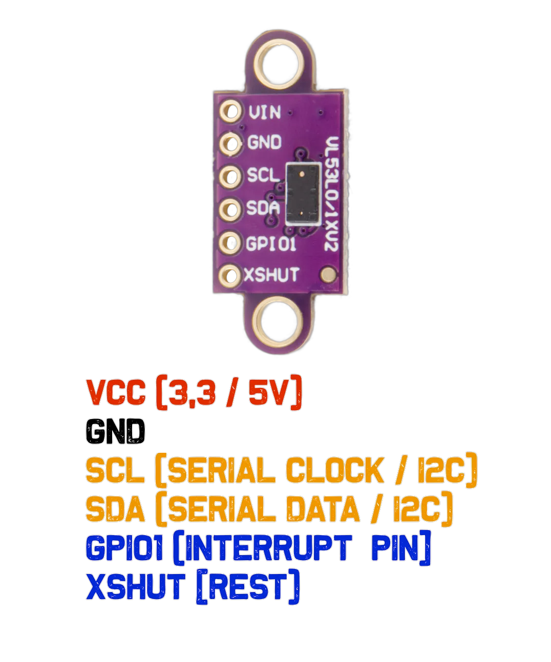
| Pin | Type | Description | Notes |
|---|---|---|---|
| VIN | Power | Power supply input (2.6V to 5.5V) | Typically 3.3V or 5V |
| GND | Ground | Ground connection | Common ground |
| SCL | I2C Clock | I2C Serial Clock line | Clock signal (requires pull-up) |
| SDA | I2C Data | I2C Serial Data line | Bidirectional data (requires pull-up) |
| XSHUT | Control | Shutdown pin (active low) | Used to reset sensor or change I2C address |
| GPIO1 | Interrupt | Interrupt output pin | Optional for event-driven measurements |
Measurement range: 30 mm to 2000 mm (2 meters), best case
Resolution: 1 mm
Field of View: ~25°
Operating voltage: 2.6V to 5.5V, dropped to 2.8V by the onboard regulator
SDA and SCL are level shifted to whatever VIN you feed the board
Board size: 12 mm x 24.6 mm including the two mounting ears
I2C address: 0x29 (default)
Same pad order, pitch and silkscreen as the plain VL53L0X module
Wiring the VL53L0X V2 to ESP32
Connect the VL53L0X V2 to your ESP32 via I2C (SDA and SCL pins). The board runs from 2.6V to 5.5V through its onboard 2.8V regulator, and its level shifters reference the I2C lines to whatever you put on VIN. Pull-up resistors are included on the module.
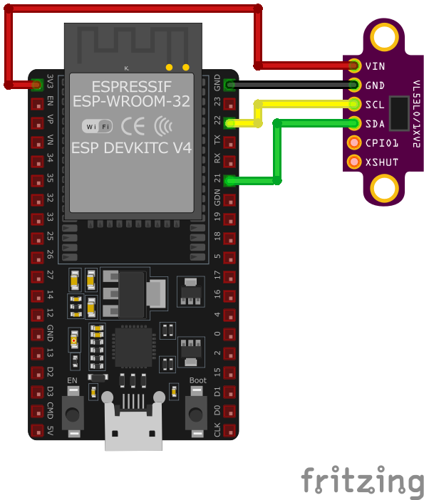
| VL53L0X V2 pin | ESP32 pin | Purpose |
|---|---|---|
| VIN | 3.3V or 5V | Power supply (2.6V to 5.5V) |
| GND | GND | Ground connection |
| SDA | GPIO21 | I2C data line (with pull-up) |
| SCL | GPIO22 | I2C clock line (with pull-up) |
| XSHUT | GPIO (optional) | Reset control for address changing · optional |
| GPIO1 | GPIO (optional) | Interrupt output for measurement ready · optional |
I2C address: 0x29 (default, changeable via XSHUT)
Pull-up resistors are included on the module
Runs from either 3.3V or 5V - the onboard regulator feeds the chip 2.8V
Clear pin labeling for easy connection
Uses the same libraries as any other VL53L0X board (Adafruit_VL53L0X)
XSHUT allows multiple sensors on same I2C bus
Avoid shiny, transparent, or very dark surfaces for best accuracy
VL53L0X V2 code examples
#include <Wire.h>
#include <Adafruit_VL53L0X.h>

Adafruit_VL53L0X lox = Adafruit_VL53L0X();

void setup() {
    Serial.begin(115200);
    Wire.begin();

    if (!lox.begin()) {
        Serial.println("Failed to initialize VL53L0X! Check connections.");
        while (1);
    }
    Serial.println("VL53L0X Initialized.");
}

void loop() {
    VL53L0X_RangingMeasurementData_t measure;
    lox.rangingTest(&measure, false);

    if (measure.RangeStatus != 4) { // Status 4 means no object detected
        Serial.print("Distance: ");
        Serial.print(measure.RangeMilliMeter);
        Serial.println(" mm");
    } else {
        Serial.println("Out of range.");
    }

    delay(500);
}
This Arduino code demonstrates how to use the VL53L0X sensor with the Adafruit library. It initializes the sensor using the lox.begin() method. In the loop(), the rangingTest() method measures the distance to an object in millimeters, which is printed to the Serial Monitor every 500 ms. If no object is detected or the object is out of range, a corresponding message is displayed. The I2C protocol facilitates communication with the sensor. The V2 board is the same VL53L0X chip on a revised breakout - the driver applies unchanged.
// Minimal raw-I2C single-shot ranging for the VL53L0X (address 0x29).
// The chip boots with usable default settings; this reads uncalibrated
// distance directly. For production accuracy, use ST's VL53L0X API.
#include <stdio.h>
#include "freertos/FreeRTOS.h"
#include "freertos/task.h"
#include "driver/i2c.h"
#define I2C_MASTER_SCL_IO 22
#define I2C_MASTER_SDA_IO 21
#define I2C_MASTER_NUM I2C_NUM_0
#define I2C_MASTER_FREQ_HZ 100000
#define VL53L0X_ADDR 0x29
#define REG_SYSRANGE_START 0x00
#define REG_RESULT_INTERRUPT_STATUS 0x13
#define REG_RESULT_RANGE_MM 0x1E // RESULT_RANGE_STATUS + 10
#define REG_SYSTEM_INTERRUPT_CLEAR 0x0B
static esp_err_t wr8(uint8_t reg, uint8_t val) {
uint8_t buf[2] = {reg, val};
return i2c_master_write_to_device(I2C_MASTER_NUM, VL53L0X_ADDR, buf, 2, pdMS_TO_TICKS(1000));
}
static esp_err_t rd(uint8_t reg, uint8_t *data, size_t len) {
return i2c_master_write_read_device(I2C_MASTER_NUM, VL53L0X_ADDR, ®, 1, data, len, pdMS_TO_TICKS(1000));
}
void app_main(void) {
i2c_config_t conf = {
.mode = I2C_MODE_MASTER,
.sda_io_num = I2C_MASTER_SDA_IO,
.scl_io_num = I2C_MASTER_SCL_IO,
.sda_pullup_en = GPIO_PULLUP_ENABLE,
.scl_pullup_en = GPIO_PULLUP_ENABLE,
.master.clk_speed = I2C_MASTER_FREQ_HZ,
};
ESP_ERROR_CHECK(i2c_param_config(I2C_MASTER_NUM, &conf));
ESP_ERROR_CHECK(i2c_driver_install(I2C_MASTER_NUM, conf.mode, 0, 0, 0));
uint8_t model_id = 0;
if (rd(0xC0, &model_id, 1) != ESP_OK || model_id != 0xEE) {
printf("VL53L0X not found (model id 0x%02X) - check wiring\n", model_id);
return;
}
printf("VL53L0X found.\n");
while (1) {
wr8(REG_SYSRANGE_START, 0x01); // Start a single-shot measurement
// Wait for the result (interrupt status bits 0-2 set when ready)
uint8_t status = 0;
for (int i = 0; i < 50; i++) {
rd(REG_RESULT_INTERRUPT_STATUS, &status, 1);
if (status & 0x07) break;
vTaskDelay(pdMS_TO_TICKS(5));
}
if (status & 0x07) {
uint8_t range[2];
rd(REG_RESULT_RANGE_MM, range, 2);
uint16_t distance = (range[0] << 8) | range[1];
if (distance < 8190) {
printf("Distance: %u mm\n", distance);
} else {
printf("Out of range\n");
}
wr8(REG_SYSTEM_INTERRUPT_CLEAR, 0x01);
} else {
printf("Measurement timeout\n");
}
vTaskDelay(pdMS_TO_TICKS(500));
}
}This is a minimal raw-I2C example: the VL53L0X boots with usable default settings, so writing 0x01 to the SYSRANGE_START register triggers a single-shot measurement, the interrupt-status register signals completion, and the 16-bit range in millimeters is read from the result registers (values around 8190 mean out of range). This gives functional but uncalibrated readings - for production accuracy (calibration, long-range/high-accuracy profiles), port ST's official VL53L0X API as an ESP-IDF component. The V2 board is the same VL53L0X chip on a revised breakout - the driver applies unchanged.
i2c:
  sda: GPIO21
  scl: GPIO22

sensor:
  - platform: vl53l0x
    name: "VL53L0X Distance"
    update_interval: 500ms
This ESPHome configuration uses the vl53l0x platform to interface with the sensor. The sensor’s name, ‘VL53L0X Distance,’ makes it easily identifiable in home automation platforms like Home Assistant. The update_interval of 500 ms ensures frequent updates for applications requiring real-time distance measurements. The V2 board is the same VL53L0X chip on a revised breakout - the driver applies unchanged.
[env:esp32dev]
platform = espressif32
board = esp32dev
framework = arduino
monitor_speed = 115200
lib_deps =
adafruit/Adafruit_VL53L0X @ ^1.2.4#include <Arduino.h>
#include <Wire.h>
#include <Adafruit_VL53L0X.h>
Adafruit_VL53L0X lox = Adafruit_VL53L0X();
void setup() {
Serial.begin(115200);
Wire.begin();
if (!lox.begin()) {
Serial.println("Failed to initialize VL53L0X! Check connections.");
while (1);
}
Serial.println("VL53L0X Initialized.");
}
void loop() {
VL53L0X_RangingMeasurementData_t measure;
lox.rangingTest(&measure, false);
if (measure.RangeStatus != 4) { // Status 4 means no object detected
Serial.print("Distance: ");
Serial.print(measure.RangeMilliMeter);
Serial.println(" mm");
} else {
Serial.println("Out of range.");
}
delay(500);
}The PlatformIO code uses the Adafruit VL53L0X library to interface with the sensor. After initializing I2C communication with Wire.begin(), the sensor is configured using lox.begin(). The rangingTest() function retrieves distance measurements in millimeters, which are printed to the Serial Monitor every 500 ms. A status check ensures meaningful data is displayed, and the code gracefully handles ‘out of range’ cases. The V2 board is the same VL53L0X chip on a revised breakout - the driver applies unchanged.
# Requires driver: VL53L0X.py from https://github.com/uceeatz/VL53L0X
# Copy it to the board: mpremote cp VL53L0X.py :
from machine import I2C, Pin
import time
import VL53L0X

# Initialize I2C (SDA=GPIO21, SCL=GPIO22)
i2c = I2C(0, scl=Pin(22), sda=Pin(21))

# Initialize VL53L0X sensor
tof = VL53L0X.VL53L0X(i2c)
tof.start()

while True:
    distance = tof.read()  # Distance in mm
    print("Distance: {} mm".format(distance))
    time.sleep(0.5)
The example uses the uceeatz/VL53L0X MicroPython driver (copy VL53L0X.py to the board). After start() begins ranging, read() returns the distance in millimeters. The sensor sits at address 0x29 on the default I2C pins. The V2 board is the same VL53L0X chip on a revised breakout - the driver applies unchanged.
VL53L0X V2 specifications
About the VL53L0X V2
Despite the name, “VL53L0X V2” is not a second-generation chip from STMicroelectronics - it is a breakout-board designation used by several Chinese board makers (sold under names like GY-VL53L0XV2, and re-badged by sellers such as DEVMO, ALAMSCN and AITRIP) for a board carrying the identical VL53L0X die as every other VL53L0X module. Same 940 nm laser, same SPAD-array time-of-flight ranging, same fixed I2C address of 0x29, same roughly 2-meter best-case range that shrinks well below that on dark or distant targets.
What the “V2” marks is a board name, not a sensor revision, and it is worth knowing how little separates it from modules sold without the label - listings on both sides routinely ship the same purple CJVL53L0XV2 PCB, roughly 12 x 24.6 mm with a mounting ear at each end and six pads reading VCC, GND, SCL, SDA, GPIO1 and XSHUT. Its useful features are the ones any decent VL53L0X carrier has: an onboard 2.8V regulator and level shifters on SDA and SCL, so it accepts 2.6V to 5.5V on VIN and talks to a 3.3V or 5V board without extra parts. Every Arduino, ESP-IDF, ESPHome, PlatformIO and MicroPython example written for the plain VL53L0X runs on it without any code changes, since the driver only ever talks to the chip’s registers.
Given that the two are electrically and functionally identical, there is no reason to pay extra for the “V2” label specifically - buy whichever VL53L0X board is cheapest, in stock, or has the pin layout that fits your project, including the GY-530 or TOF200C variants of the same chip. The only sensor worth stepping up to for a real capability gain is the longer-range VL53L1X, which reaches roughly twice the distance in good conditions.
VL53L0X V2 troubleshooting
Sensor Not Detected on I²C Bus
›
Issue: VL53L0X not showing on I²C bus.
Solution: Check that XSHUT is tied high and that SDA/SCL are correctly connected. Scan for address with I²C scanner.
Inaccurate or Unstable Readings
›
Issue: Sensor gives fluctuating values.
Solution: Try averaging measurements and avoid reflective or dark objects too close to the sensor.
Always Reads Maximum Distance
›
Issue: Constant 2000 mm or 0 mm readings.
Solution: Ensure object is within range and directly in front of the sensor. Add a delay between readings.
Where to buy the VL53L0X V2

Resources
Similar sensors


