
HC-SR04 Ultrasonic Distance Sensor
The HC-SR04 is a versatile ultrasonic distance sensor capable of measuring distances up to 4 meters with high precision. It is widely used in robotics and automation applications due to its low cost and simple operation. The sensor's compact design and efficient performance make it an excellent choice for both hobbyist and professional projects.

HC-SR04 pinout
The HC-SR04 features a simple 4-pin design for power and trigger/echo ultrasonic measurement.
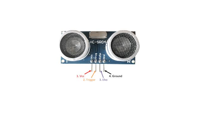
| Pin | Type | Description | Notes |
|---|---|---|---|
| VCC | Power | Power supply input (5V required) | Requires stable 5V power supply |
| GND | Power | Ground connection | Connect to ESP32 ground |
| TRIG | Control | Trigger input pin | Send 10µs pulse to initiate measurement |
| ECHO | Communication | Echo output pin | Returns pulse width proportional to distance |
Requires 5V power - most ESP32 boards provide this
ECHO pin outputs 5V - use voltage divider for 3.3V ESP32
Measures 2cm to 400cm with ±3mm accuracy
Uses ultrasonic sound waves (40kHz)
Measurement takes about 10-25ms
Wiring the HC-SR04 to ESP32
Connect the HC-SR04 with voltage divider for ECHO pin to protect 3.3V ESP32 GPIO.
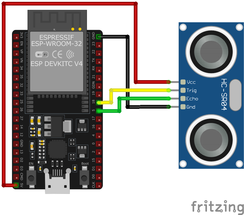
| HC-SR04 pin | ESP32 pin | Purpose |
|---|---|---|
| VCC | 5V | 5V power supply required |
| GND | GND | Ground connection |
| TRIG | GPIO5 | Trigger input (can handle 3.3V logic) |
| ECHO | GPIO18 | Echo output (use voltage divider) |
| ECHO (Divider) | 1kΩ + 2kΩ | Voltage divider to convert 5V to 3.3V |
ECHO pin outputs 5V - can damage 3.3V ESP32 GPIO
Use voltage divider: 1kΩ (ECHO to GPIO) + 2kΩ (GPIO to GND)
TRIG pin accepts 3.3V logic directly
Send 10µs HIGH pulse on TRIG to start measurement
ECHO pulse width in µs ÷ 58 = distance in cm
HC-SR04 code examples
#define TRIG_PIN 5
#define ECHO_PIN 18

void setup() {
    Serial.begin(115200);
    pinMode(TRIG_PIN, OUTPUT);
    pinMode(ECHO_PIN, INPUT);
    Serial.println("HC-SR04 Distance Sensor Example");
}

void loop() {
    long duration;
    float distance;

    // Trigger the sensor
    digitalWrite(TRIG_PIN, LOW);
    delayMicroseconds(2);
    digitalWrite(TRIG_PIN, HIGH);
    delayMicroseconds(10);
    digitalWrite(TRIG_PIN, LOW);

    // Read the Echo pin
    duration = pulseIn(ECHO_PIN, HIGH);

    // Calculate distance in cm
    distance = duration * 0.034 / 2;

    Serial.print("Distance: ");
    Serial.print(distance);
    Serial.println(" cm");

    delay(500);
}
This Arduino sketch demonstrates how to use the HC-SR04 sensor for distance measurement. The TRIG_PIN and ECHO_PIN are defined to connect the sensor to GPIO pins 5 and 18, respectively. The setup() function initializes these pins and configures the Serial Monitor. In the loop(), a 10 µs pulse is sent to the Trigger pin to start measurement, and the duration of the Echo pin’s HIGH state is measured using the pulseIn() function. The distance is calculated using the formula duration * 0.034 / 2, which converts the time into distance in centimeters.
#include <stdio.h>
#include "esp_rom_sys.h"
#include "freertos/FreeRTOS.h"
#include "freertos/task.h"
#include "driver/gpio.h"
#include "esp_timer.h"

#define TRIG_PIN GPIO_NUM_5
#define ECHO_PIN GPIO_NUM_18

void app_main() {
    gpio_set_direction(TRIG_PIN, GPIO_MODE_OUTPUT);
    gpio_set_direction(ECHO_PIN, GPIO_MODE_INPUT);

    while (1) {
        // Send trigger pulse
        gpio_set_level(TRIG_PIN, 0);
        esp_rom_delay_us(2);
        gpio_set_level(TRIG_PIN, 1);
        esp_rom_delay_us(10);
        gpio_set_level(TRIG_PIN, 0);

        // Measure echo pulse width
        uint64_t start_time = esp_timer_get_time();
        while (!gpio_get_level(ECHO_PIN)); // Wait for HIGH
        uint64_t echo_start = esp_timer_get_time();
        while (gpio_get_level(ECHO_PIN)); // Wait for LOW
        uint64_t echo_end = esp_timer_get_time();

        uint64_t duration = echo_end - echo_start;
        float distance = (duration * 0.034) / 2;

        printf("Distance: %.2f cm\n", distance);

        vTaskDelay(pdMS_TO_TICKS(500));
    }
}
This ESP-IDF code configures GPIO pins for the Trigger and Echo of the HC-SR04 sensor. The gpio_set_level() function sends a 10 µs pulse to the Trigger pin. The time taken for the Echo pin to go HIGH and then LOW is measured using esp_timer_get_time(), which provides timestamps in microseconds. The distance is calculated based on the formula (duration * 0.034) / 2. The program continuously measures and prints the distance in centimeters every 500 ms.
sensor:
  - platform: ultrasonic
    trigger_pin: 5
    echo_pin: 18
    name: "HC-SR04 Distance"
    update_interval: 500ms
    accuracy_decimals: 1
    timeout: 2.0m
The ESPHome configuration uses the ultrasonic platform to interface with the HC-SR04 sensor. The trigger_pin and echo_pin specify the GPIO pins connected to the sensor. The name assigns a user-friendly identifier (‘HC-SR04 Distance’) for use in platforms like Home Assistant. The update_interval of 500 ms specifies how often distance measurements are taken, while accuracy_decimals ensures measurements are displayed to one decimal place. The timeout prevents errors in case of no response within the specified time.
[env:esp32dev]
platform = espressif32
board = esp32dev
framework = arduino
monitor_speed = 115200#include <Arduino.h>
#define TRIG_PIN 5
#define ECHO_PIN 18
void setup() {
Serial.begin(115200);
pinMode(TRIG_PIN, OUTPUT);
pinMode(ECHO_PIN, INPUT);
Serial.println("HC-SR04 Distance Sensor Example");
}
void loop() {
long duration;
float distance;
// Trigger the sensor
digitalWrite(TRIG_PIN, LOW);
delayMicroseconds(2);
digitalWrite(TRIG_PIN, HIGH);
delayMicroseconds(10);
digitalWrite(TRIG_PIN, LOW);
// Read the Echo pin
duration = pulseIn(ECHO_PIN, HIGH);
// Calculate distance in cm
distance = duration * 0.034 / 2;
Serial.print("Distance: ");
Serial.print(distance);
Serial.println(" cm");
delay(500);
}The PlatformIO code is identical to the Arduino example, making it compatible with ESP32 boards configured via the PlatformIO environment. It uses TRIG_PIN and ECHO_PIN for sensor operation. A short 10 µs pulse triggers the measurement, and the pulse duration is read on the Echo pin using the pulseIn() function. The calculated distance is printed to the Serial Monitor every 500 ms.
from machine import Pin, time_pulse_us
from time import sleep

# Define pins for Trigger and Echo
TRIG_PIN = 5
ECHO_PIN = 18

# Initialize Trigger and Echo pins
trig = Pin(TRIG_PIN, Pin.OUT)
echo = Pin(ECHO_PIN, Pin.IN)

def measure_distance():
    # Send a 10 µs pulse to the Trigger pin
    trig.low()
    sleep(0.000002)  # 2 µs
    trig.high()
    sleep(0.00001)  # 10 µs
    trig.low()

    # Measure the duration of the Echo pulse
    duration = time_pulse_us(echo, 1, 30000)  # Timeout after 30 ms (no response)

    # Calculate distance in cm (speed of sound = 343 m/s)
    distance = (duration * 0.0343) / 2
    return distance

print("HC-SR04 Distance Sensor Example")

while True:
    distance = measure_distance()
    if distance > 0:
        print("Distance: {:.2f} cm".format(distance))
    else:
        print("Out of range or no object detected.")
    sleep(0.5)
This MicroPython script interfaces with the HC-SR04 sensor using Trigger and Echo pins. The Trigger pin sends a 10 µs pulse to initiate the measurement, while the Echo pin receives a pulse whose width corresponds to the distance measured. The time_pulse_us() function measures the duration of the Echo pulse in microseconds, with a timeout of 30 ms to prevent infinite waiting. The distance is calculated using the formula (duration * 0.0343) / 2, where 0.0343 cm/µs is the speed of sound. The script continuously measures and prints the distance to the console every 500 ms. If no response is detected, it prints an ‘Out of range’ message.
HC-SR04 specifications
About the HC-SR04
The HC-SR04 is the classic budget ultrasonic distance sensor: a pair of transducers behind a trigger/echo digital interface that has become the default teaching example for pulse timing on Arduino and ESP32 alike. Send a 10 microsecond HIGH pulse on TRIG and the sensor replies on ECHO with a pulse whose width is proportional to round-trip travel time; the standard math (duration in microseconds x 0.034 / 2) converts that into centimeters, assuming a fixed speed of sound of 343 m/s. That number actually depends on air temperature - closer to 331 m/s at freezing and 355 m/s at 40 degC - so the fixed constant drifts by a few percent across a typical outdoor temperature swing; fine for a hobby proximity trigger, worth compensating for if precision across seasons actually matters.
The one wiring detail that trips up first-time ESP32 users: the HC-SR04 needs a full 5V supply, and its ECHO pin also outputs a 5V pulse, which is out of spec for the ESP32’s 3.3V-only GPIOs. A simple resistor divider (1 kOhm in series, 2 kOhm to ground) on ECHO brings that down to a safe level; skip it and there is a real risk of damaging the input. TRIG, being an output from the ESP32, needs no such protection.
At around 1.5 dollars it is hard to beat on price, but it is not sealed against moisture and has a comparatively wide 2 cm blind zone. For anything that has to survive rain or a wash-down, the waterproof JSN-SR04T uses the same protocol and math with a sealed probe on a cable, and the UART-based A02YYUW goes further still by skipping the trigger/echo timing and the 5V hazard entirely, at a higher price.
HC-SR04 troubleshooting
Sensor Returns Zero or No Readings
›
Issue: The HC-SR04 ultrasonic sensor consistently returns zero or no distance measurements.
Possible causes include incorrect wiring, insufficient power supply, or faulty sensor hardware.
Solution: Verify that the VCC pin is connected to a stable 5V power source and the GND pin to ground. Ensure that the TRIG and ECHO pins are connected to the appropriate digital I/O pins on the microcontroller. Check for secure and correct connections, and consider testing the sensor with a different microcontroller or setup to rule out hardware defects.
Inaccurate or Fluctuating Distance Measurements
›
Issue: The sensor provides inconsistent or incorrect distance readings.
Possible causes include environmental factors such as soft or angled target surfaces, electrical noise, or interference from nearby ultrasonic sensors.
Solution: Ensure that the target surface is hard and perpendicular to the sensor for optimal reflection. Implement averaging of multiple readings in your code to mitigate occasional erroneous data. Maintain a clear line of sight between the sensor and the target, and avoid operating multiple ultrasonic sensors in close proximity to prevent cross-talk interference.
Sensor Not Detected or Unresponsive
›
Issue: The microcontroller fails to detect the HC-SR04 sensor, or the sensor does not respond to trigger signals.
Possible causes include incorrect pin assignments in the code, lack of proper initialization, or defective sensor module.
Solution: Double-check the pin assignments in your code to ensure they match the physical connections. Confirm that the sensor is properly initialized in the setup section of your code. If the issue persists, test the sensor with a known working setup or replace it to rule out hardware failure.
Interference from Environmental Factors
›
Issue: External factors cause the sensor to produce unreliable readings.
Possible causes include high ambient noise levels, temperature variations, or obstacles in the sensor's field of view.
Solution: Operate the sensor in a controlled environment to minimize acoustic and electrical noise. Be aware that temperature changes can affect the speed of sound; consider implementing temperature compensation if precise measurements are required. Ensure that there are no unintended obstacles within the sensor's detection range that could cause false readings.
Where to buy the HC-SR04

Resources
Similar sensors


