
AGS10 Sensor
The AGS10 is a gas sensor known for detecting a range of gases, including methane, propane, and hydrogen. Designed with stability and sensitivity, it’s suitable for industrial safety and environmental monitoring. The sensor offers a rapid response time, high sensitivity, and low power consumption, often used in applications like leak detection and air quality monitoring systems.

AGS10 pinout
The AGS10 exposes a plain 4-pin I2C interface at address 0x1A. Its unusual constraints are electrical rather than mechanical: a 3.0 V ±0.1 V supply and an I2C clock of 15 kHz or less.
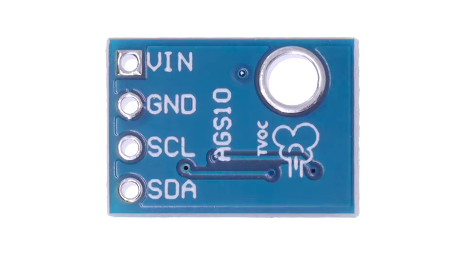
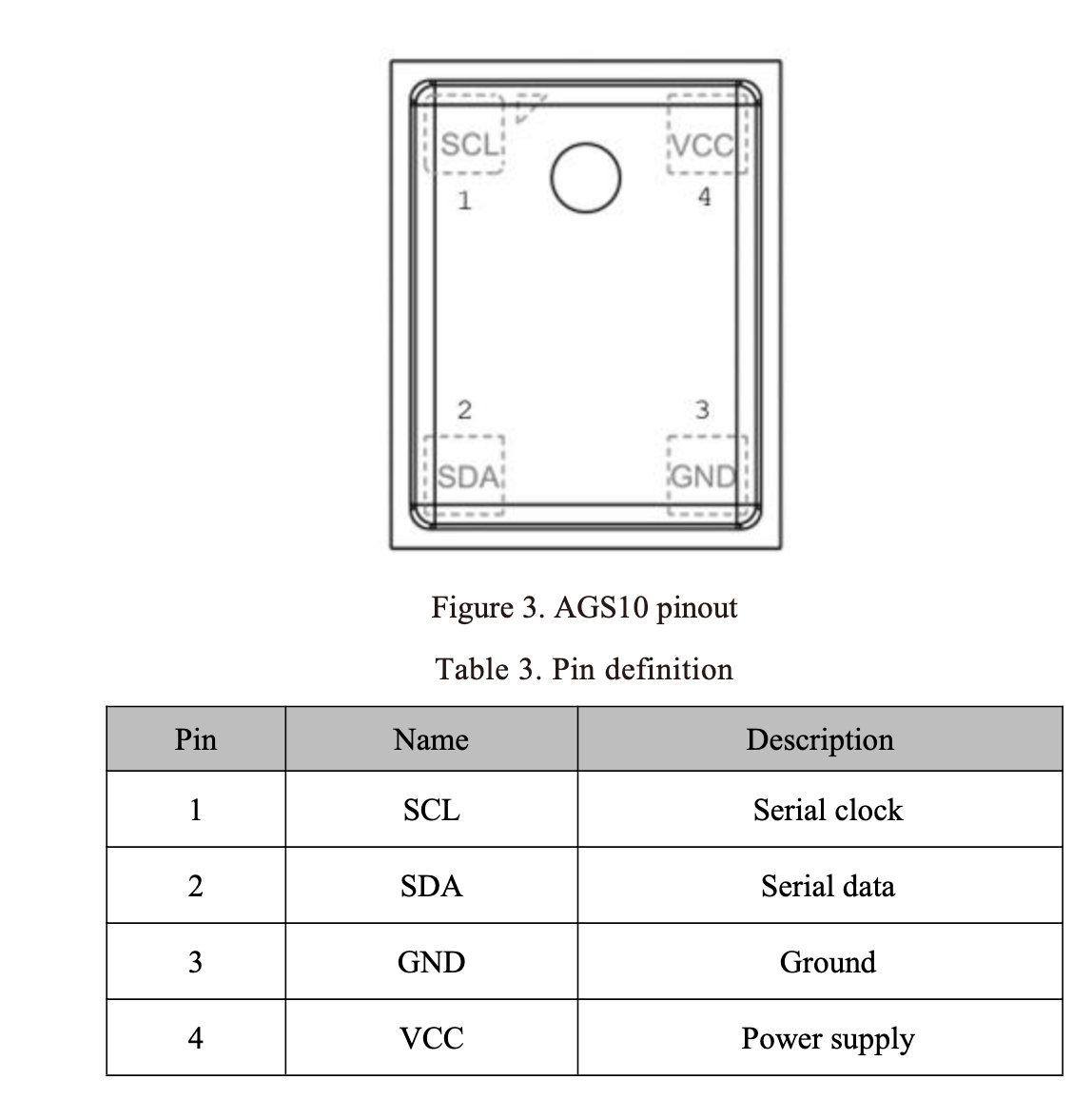
| Pin | Type | Description | Notes |
|---|---|---|---|
| VDD | Power | Power supply (datasheet specifies 3.0 V +-0.1 V) | A bare module without its own regulator should not be assumed happy on a plain 3.3 V rail |
| GND | Power | Ground connection | Connect to ESP32 ground |
| SDA | Communication | I2C data line | Bus clock must be 15 kHz or slower |
| SCL | Communication | I2C clock line | Bus clock must be 15 kHz or slower |
Wiring the AGS10 to ESP32
Connect the AGS10 over I2C on the ESP32’s default bus pins - the diagram shows a Heltec WiFi LoRa 32 board, but any ESP32 works the same way. Slow the bus to 15 kHz or less before talking to the sensor.
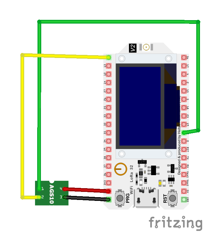
| AGS10 pin | ESP32 pin | Purpose |
|---|---|---|
| VDD | 3.3V | Power supply (datasheet spec is 3.0 V +-0.1 V - see notes) |
| GND | GND | Ground connection |
| SDA | GPIO21 | I2C data line (default SDA) |
| SCL | GPIO22 | I2C clock line (default SCL) |
Set the I2C clock to 15 kHz or less (Wire.setClock(15000); ESPHome: frequency: 10kHz) - skipping this is the most common AGS10 integration mistake
The datasheet calls for a regulated 3.0 V ±0.1 V supply; modules with an onboard regulator can take 3.3 V, a bare sensor is out of spec on a plain 3.3 V rail
I2C address is 0x1A
AGS10 code examples
// The AGS10 answers directly with a 5-byte TVOC report - no external library needed.
// I2C address 0x1A; the sensor requires a SLOW I2C clock (15 kHz or less).
#include <Wire.h>

#define AGS10_ADDR 0x1A

// CRC-8, polynomial 0x31, init 0xFF (per AGS10 datasheet)
uint8_t ags10_crc(const uint8_t *data, int len) {
  uint8_t crc = 0xFF;
  for (int i = 0; i < len; i++) {
    crc ^= data[i];
    for (int b = 0; b < 8; b++)
      crc = (crc & 0x80) ? (crc << 1) ^ 0x31 : crc << 1;
  }
  return crc;
}

void setup() {
  Serial.begin(115200);
  Wire.begin();          // SDA=GPIO21, SCL=GPIO22
  Wire.setClock(15000);  // AGS10 maximum I2C speed is 15 kHz
  Serial.println("AGS10 TVOC Sensor Example");
}

void loop() {
  // Reading returns: status, TVOC (3 bytes, big-endian, ppb), CRC
  Wire.requestFrom(AGS10_ADDR, 5);
  if (Wire.available() == 5) {
    uint8_t b[5];
    for (int i = 0; i < 5; i++) b[i] = Wire.read();

    if (ags10_crc(b, 4) != b[4]) {
      Serial.println("CRC error - check wiring and I2C speed");
    } else if (b[0] & 0x01) {
      Serial.println("Sensor not ready (warming up)");
    } else {
      uint32_t tvoc = ((uint32_t)b[1] << 16) | ((uint32_t)b[2] << 8) | b[3];
      Serial.print("TVOC: ");
      Serial.print(tvoc);
      Serial.println(" ppb");
    }
  } else {
    Serial.println("No response from AGS10");
  }
  delay(3000); // Datasheet requires at least 2 seconds between reads
}
The AGS10 needs no external library - it answers a plain I2C read with 5 bytes: a status byte, a 24-bit TVOC value in ppb, and a CRC-8 checksum, which the sketch verifies before printing. Two quirks matter: the sensor's I2C clock must stay at or below 15 kHz (Wire.setClock(15000)), and reads must be at least 2 seconds apart. Expect a warm-up period after power-on while the status byte reports not-ready.
// The AGS10 answers a plain I2C read with 5 bytes: status, 24-bit TVOC (ppb), CRC.
// Note: the sensor requires a SLOW I2C clock (15 kHz or less) and at least
// 2 seconds between reads.
#include <stdio.h>
#include "freertos/FreeRTOS.h"
#include "freertos/task.h"
#include "driver/i2c.h"

#define I2C_MASTER_SCL_IO  22
#define I2C_MASTER_SDA_IO  21
#define I2C_MASTER_NUM     I2C_NUM_0
#define I2C_MASTER_FREQ_HZ 15000   // AGS10 maximum I2C speed
#define AGS10_ADDR         0x1A

// CRC-8, polynomial 0x31, init 0xFF (per AGS10 datasheet)
static uint8_t ags10_crc(const uint8_t *data, int len) {
    uint8_t crc = 0xFF;
    for (int i = 0; i < len; i++) {
        crc ^= data[i];
        for (int b = 0; b < 8; b++)
            crc = (crc & 0x80) ? (crc << 1) ^ 0x31 : crc << 1;
    }
    return crc;
}

void app_main(void) {
    i2c_config_t conf = {
        .mode = I2C_MODE_MASTER,
        .sda_io_num = I2C_MASTER_SDA_IO,
        .scl_io_num = I2C_MASTER_SCL_IO,
        .sda_pullup_en = GPIO_PULLUP_ENABLE,
        .scl_pullup_en = GPIO_PULLUP_ENABLE,
        .master.clk_speed = I2C_MASTER_FREQ_HZ,
    };
    ESP_ERROR_CHECK(i2c_param_config(I2C_MASTER_NUM, &conf));
    ESP_ERROR_CHECK(i2c_driver_install(I2C_MASTER_NUM, conf.mode, 0, 0, 0));

    while (1) {
        uint8_t data[5];
        if (i2c_master_read_from_device(I2C_MASTER_NUM, AGS10_ADDR, data, 5, pdMS_TO_TICKS(1000)) == ESP_OK) {
            if (ags10_crc(data, 4) != data[4]) {
                printf("CRC error - check wiring and I2C speed\n");
            } else if (data[0] & 0x01) {
                printf("Sensor not ready (warming up)\n");
            } else {
                uint32_t tvoc = ((uint32_t)data[1] << 16) | ((uint32_t)data[2] << 8) | data[3];
                printf("TVOC: %lu ppb\n", (unsigned long)tvoc);
            }
        } else {
            printf("No response from AGS10\n");
        }
        vTaskDelay(pdMS_TO_TICKS(3000)); // At least 2 s between reads
    }
}
The AGS10 needs no external component - it answers a plain I2C read with 5 bytes: a status byte, a 24-bit TVOC value in ppb, and a CRC-8 checksum (polynomial 0x31), which the example verifies before printing. Two quirks matter: the sensor's I2C clock must stay at or below 15 kHz (hence I2C_MASTER_FREQ_HZ 15000), and reads must be at least 2 seconds apart. Expect a warm-up period after power-on while the status byte reports not-ready.
i2c:
  frequency: 10kHz  # the AGS10 requires 15 kHz or less
  sda: GPIO21
  scl: GPIO22

sensor:
  - platform: ags10
    tvoc:
name: TVOC[env:esp32dev]
platform = espressif32
board = esp32dev
framework = arduino
monitor_speed = 115200#include <Arduino.h>
// The AGS10 answers directly with a 5-byte TVOC report - no external library needed.
// I2C address 0x1A; the sensor requires a SLOW I2C clock (15 kHz or less).
#include <Wire.h>
#define AGS10_ADDR 0x1A
// CRC-8, polynomial 0x31, init 0xFF (per AGS10 datasheet)
uint8_t ags10_crc(const uint8_t *data, int len) {
uint8_t crc = 0xFF;
for (int i = 0; i < len; i++) {
crc ^= data[i];
for (int b = 0; b < 8; b++)
crc = (crc & 0x80) ? (crc << 1) ^ 0x31 : crc << 1;
}
return crc;
}
void setup() {
Serial.begin(115200);
Wire.begin(); // SDA=GPIO21, SCL=GPIO22
Wire.setClock(15000); // AGS10 maximum I2C speed is 15 kHz
Serial.println("AGS10 TVOC Sensor Example");
}
void loop() {
// Reading returns: status, TVOC (3 bytes, big-endian, ppb), CRC
Wire.requestFrom(AGS10_ADDR, 5);
if (Wire.available() == 5) {
uint8_t b[5];
for (int i = 0; i < 5; i++) b[i] = Wire.read();
if (ags10_crc(b, 4) != b[4]) {
Serial.println("CRC error - check wiring and I2C speed");
} else if (b[0] & 0x01) {
Serial.println("Sensor not ready (warming up)");
} else {
uint32_t tvoc = ((uint32_t)b[1] << 16) | ((uint32_t)b[2] << 8) | b[3];
Serial.print("TVOC: ");
Serial.print(tvoc);
Serial.println(" ppb");
}
} else {
Serial.println("No response from AGS10");
}
delay(3000); // Datasheet requires at least 2 seconds between reads
}This code is the same as the Arduino code but is intended for use with the PlatformIO environment. It initializes the I2C communication with the AGS10 sensor, reads data, and prints it to the Serial Monitor. Ensure the PlatformIO environment is correctly set up with the specified settings in the platformio.ini file.
from machine import I2C, Pin
from time import sleep

# The AGS10 requires a SLOW I2C clock (15 kHz or less) and answers a plain
# 5-byte read: status, 24-bit TVOC (ppb), CRC-8 - no driver needed.
i2c = I2C(0, scl=Pin(22), sda=Pin(21), freq=10000)
AGS10_ADDR = 0x1A

def crc8(data):
    crc = 0xFF
    for b in data:
        crc ^= b
        for _ in range(8):
            crc = ((crc << 1) ^ 0x31) & 0xFF if crc & 0x80 else (crc << 1) & 0xFF
    return crc

while True:
    data = i2c.readfrom(AGS10_ADDR, 5)
    if crc8(data[:4]) != data[4]:
        print("CRC error - check wiring and I2C speed")
    elif data[0] & 0x01:
        print("Sensor not ready (warming up)")
    else:
        tvoc = (data[1] << 16) | (data[2] << 8) | data[3]
        print("TVOC: {} ppb".format(tvoc))
    sleep(3)  # at least 2 seconds between reads
The AGS10 needs no driver - it answers a plain 5-byte I2C read: a status byte, a 24-bit TVOC value in ppb, and a CRC-8 checksum which the example verifies. Two quirks matter: the I2C clock must stay at or below 15 kHz (freq=10000), and reads must be at least 2 seconds apart. Expect a warm-up period while the status byte reports not-ready.
AGS10 specifications
About the AGS10
The AGS10 is Aosong’s (branded Asair) factory-calibrated TVOC sensor: a metal-oxide element on a MEMS heater plate, with the analog front end and calibration handled on-chip so it answers over I2C with a ready-made total-VOC number in parts per billion, no host-side calculation needed. That number is calibrated against ethanol as the reference gas, per Aosong’s own datasheet, so a reading is really an ethanol-equivalent TVOC estimate - a useful trend indicator for indoor air quality, not a measurement of one specific chemical.
Two numbers matter more than usual for wiring this one up. First, the I2C bus has to run at 15 kHz or slower - the datasheet lists the output mode as I2C slave mode capped at 15 kHz, well under the 100 kHz most microcontrollers default to, and it is the single most common integration mistake with this sensor. Second, the AGS10 wants a tightly regulated 3.0 V ±0.1 V supply rather than a plain 3.3 V rail, so a bare module without its own regulator should be fed accordingly. Give it the datasheet’s 120-second preheat before trusting a reading, and note that its stated accuracy is only 25% of reading - workable for spotting a VOC trend, not for anything needing a precise ppb figure.
For a sensor that also computes a finished air-quality index rather than a bare TVOC number, ENS160 runs a similar on-chip MOX approach but adds eCO2 and an AQI output alongside TVOC.
AGS10 troubleshooting
CRC Error on ESP32-S2
›
Issue: When using the AGS10 sensor with an ESP32-S2 microcontroller, the following error is encountered: The crc check failed. This issue arises despite the sensor functioning correctly on standard ESP32 boards.
Possible causes include the AGS10 sensor's requirement for an I2C bus speed not exceeding 15kHz, which may not be properly configured on the ESP32-S2.
Solution: Ensure that the I2C bus frequency is explicitly set to 15kHz in your configuration. In ESPHome, this can be achieved by specifying frequency: 15kHz in the I2C setup. Additionally, verify that the ESP32-S2 supports the specified I2C frequency and that there are no hardware limitations affecting communication.
Connection Issues with TCA9548A Multiplexer
›
Issue: Integrating the AGS10 sensor with a TCA9548A I2C multiplexer in ESPHome results in configuration errors, such as: required key not provided.
Possible causes include incorrect or incomplete configuration settings in the ESPHome YAML file, particularly when defining the multiplexer channels.
Solution: Review the ESPHome configuration to ensure that all required keys and parameters are correctly specified. Each multiplexer channel should be properly defined with the necessary settings. Consulting the ESPHome documentation for guidance on configuring I2C multiplexers can provide clarity.
Compilation Errors with AGS10 Library
›
Issue: When compiling code that includes the AGS10 sensor library, errors such as: invalid conversion from 'uint8_t' {aka 'unsigned char'} to 'uint8_t*' {aka 'unsigned char*'} occur.
Possible causes include incompatibilities in the AGS10 library when used with certain microcontrollers, such as boards other than the Arduino Uno.
Solution: Consider using a modified version of the AGS10 library that addresses these compatibility issues. For instance, a fork of the library tailored for ESP32 is available and may resolve the compilation errors.
Incorrect I2C Bus Frequency Configuration
›
Issue: The AGS10 sensor requires an I2C bus speed not exceeding 15kHz. Failure to configure this can lead to communication errors or sensor malfunction.
Possible causes include the default I2C bus frequency being set higher than the sensor's specifications.
Solution: Explicitly set the I2C bus frequency to 15kHz in your microcontroller's configuration. In ESPHome, this can be done by adding frequency: 15kHz to the I2C configuration section.
Where to buy the AGS10

Resources
Similar sensors


