KY-009 RGB Full Color LED SMD Module

View on Amazon
Overview


About KY-009 RGB Full Color LED SMD Module
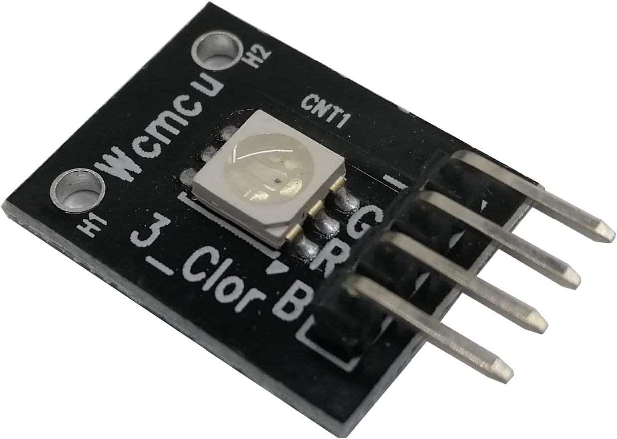
The KY-009 RGB Full Color LED SMD Module features a 5050 SMD LED capable of emitting a wide range of colors by mixing red, green, and blue light. Each color’s intensity can be adjusted using Pulse Width Modulation (PWM), allowing for the creation of nearly any color in the visible spectrum. The module operates at a voltage of 5V, with forward voltages of 1.8V for the red LED and 2.8V for the green and blue LEDs. It is compatible with microcontrollers such as Arduino, Raspberry Pi, and ESP32.
Get Your KY-009
Starting from
1$ per unit


Prices are subject to change. We earn from qualifying purchases as an Amazon Associate.
KY-009 Specifications
Complete technical specification details for KY-009 RGB Full Color LED SMD Module
📊 Technical Parameters
KY-009 Pinout
The **KY-009** is a 4-pin RGB LED module with 5050 SMD LED (common cathode):
Visual Pinout Diagram

Pin Types
Quick Tips
**Interface**: PWM control for each color channel,🌈 **Colors**: 16.7 million colors via RGB mixing
**LED Type**: 5050 SMD (surface mount device),⚡ **Power**: 5V operation, common cathode configuration
**Resistors**: R=180Ω (1.8V), G=100Ω (2.8V), B=100Ω (2.8V),🎯 **Applications**: Status indicators, mood lighting, color displays, decorative effects
Pin Descriptions
| Pin Name | Type | Description | Notes |
|---|---|---|---|
1 Pin (-) | Power | Common cathode (ground) | Shared ground for all LEDs |
2 Pin (R) | Communication | Red LED anode | 1.8V forward voltage, 180Ω resistor |
3 Pin (G) | Communication | Green LED anode | 2.8V forward voltage, 100Ω resistor |
4 Pin (B) | Communication | Blue LED anode | 2.8V forward voltage, 100Ω resistor |
Wiring KY-009 to ESP32
To interface the **KY-009** with an **ESP32** for RGB color control:
Visual Wiring Diagram

Connection Status
Protocol
Pin Connections
| KY-009 Pin | Connection | ESP32 Pin | Description |
|---|---|---|---|
1 Pin (-) Required | GND | Common ground | |
2 Pin (R) Required | GPIO18 | Red channel (via 180Ω resistor) | |
3 Pin (G) Required | GPIO19 | Green channel (via 100Ω resistor) | |
4 Pin (B) Required | GPIO21 | Blue channel (via 100Ω resistor) |
**Current-Limiting Resistors Required**: Red=180Ω, Green/Blue=100Ω for LED protection
**PWM Control**: Use PWM on all three GPIO pins for smooth color transitions
**GPIO Selection**: Use any PWM-capable GPIOs, shown pins are examples
**Brightness**: Adjust PWM duty cycle for brightness control
KY-009 Troubleshooting
Common issues and solutions to help you get your sensor working
Common Issues
Issue: The LED does not emit light when expected.
Solutions:
- Ensure all connections are secure and correctly wired.
- Verify that the appropriate current-limiting resistors are used to prevent LED damage.
- Check that the microcontroller's GPIO pins are configured as outputs and are providing the correct PWM signals.
Issue: The LED displays unexpected colors or does not mix colors correctly.
Solutions:
- Confirm that the PWM signals are correctly set for each color channel.
- Ensure that the resistors used for each LED are of appropriate values to balance brightness.
- Check for any software errors in the code controlling the PWM outputs.
Debugging Tips
Use the Serial Monitor to check for error messages and verify the sensor's output. Add debug prints in your code to track the sensor's state.
Use a multimeter to verify voltage levels and check for continuity in your connections. Ensure the power supply is stable and within the sensor's requirements.
Additional Resources
KY-009 Programming Examples
Ready-to-use code examples for different platforms and frameworks
int redPin = 9;
int greenPin = 10;
int bluePin = 11;

void setup() {
    pinMode(redPin, OUTPUT);
    pinMode(greenPin, OUTPUT);
    pinMode(bluePin, OUTPUT);
}

void loop() {
    setColor(255, 0, 0); // Red
    delay(1000);
    setColor(0, 255, 0); // Green
    delay(1000);
    setColor(0, 0, 255); // Blue
    delay(1000);
    setColor(255, 255, 0); // Yellow
    delay(1000);
    setColor(0, 255, 255); // Cyan
    delay(1000);
    setColor(255, 0, 255); // Magenta
    delay(1000);
    setColor(255, 255, 255); // White
    delay(1000);
}

void setColor(int red, int green, int blue) {
    analogWrite(redPin, red);
    analogWrite(greenPin, green);
    analogWrite(bluePin, blue);
}
This Arduino code defines pins 9, 10, and 11 for controlling the red, green, and blue channels of the KY-009 module, respectively. The setColor() function sets the brightness of each color using PWM, allowing the LED to display various colors. The loop() function cycles through several colors with a one-second delay between each.
#include <stdio.h>
#include "freertos/FreeRTOS.h"
#include "freertos/task.h"
#include "driver/ledc.h"

#define RED_PIN GPIO_NUM_18
#define GREEN_PIN GPIO_NUM_19
#define BLUE_PIN GPIO_NUM_21
#define LEDC_TIMER LEDC_TIMER_0
#define LEDC_MODE LEDC_HIGH_SPEED_MODE
#define LEDC_CHANNEL_R LEDC_CHANNEL_0
#define LEDC_CHANNEL_G LEDC_CHANNEL_1
#define LEDC_CHANNEL_B LEDC_CHANNEL_2

void configure_led_pwm(gpio_num_t pin, ledc_channel_t channel) {
    ledc_timer_config_t ledc_timer = {
        .speed_mode = LEDC_MODE,
        .timer_num = LEDC_TIMER,
        .duty_resolution = LEDC_TIMER_10_BIT,
        .freq_hz = 1000
    };
    ledc_timer_config(&ledc_timer);

    ledc_channel_config_t ledc_channel = {
        .gpio_num = pin,
        .speed_mode = LEDC_MODE,
        .channel = channel,
        .intr_type = LEDC_INTR_DISABLE,
        .timer_sel = LEDC_TIMER,
        .duty = 0,
        .hpoint = 0
    };
    ledc_channel_config(&ledc_channel);
}

void set_color(uint32_t red, uint32_t green, uint32_t blue) {
    ledc_set_duty(LEDC_MODE, LEDC_CHANNEL_R, red);
    ledc_update_duty(LEDC_MODE, LEDC_CHANNEL_R);
    ledc_set_duty(LEDC_MODE, LEDC_CHANNEL_G, green);
    ledc_update_duty(LEDC_MODE, LEDC_CHANNEL_G);
    ledc_set_duty(LEDC_MODE, LEDC_CHANNEL_B, blue);
    ledc_update_duty(LEDC_MODE, LEDC_CHANNEL_B);
}

void app_main(void) {
    configure_led_pwm(RED_PIN, LEDC_CHANNEL_R);
    configure_led_pwm(GREEN_PIN, LEDC_CHANNEL_G);
    configure_led_pwm(BLUE_PIN, LEDC_CHANNEL_B);

    while (1) {
        set_color(1023, 0, 0);  // Red
        vTaskDelay(pdMS_TO_TICKS(1000));
        set_color(0, 1023, 0);  // Green
        vTaskDelay(pdMS_TO_TICKS(1000));
        set_color(0, 0, 1023);  // Blue
        vTaskDelay(pdMS_TO_TICKS(1000));
    }
}
This ESP-IDF code configures the KY-009 RGB LED module using PWM on GPIO18 (red), GPIO19 (green), and GPIO21 (blue). The configure_led_pwm() function sets up PWM for each LED channel, and set_color() controls the brightness levels. The main loop cycles through red, green, and blue colors with one-second intervals.
output:
  - platform: ledc
    pin: GPIO18
    id: red_led
  - platform: ledc
    pin: GPIO19
    id: green_led
  - platform: ledc
    pin: GPIO21
    id: blue_led

light:
  - platform: monochromatic
    name: "KY-009 RGB LED"
    output: red_led
    gamma_correct: 2.8
  - platform: monochromatic
    name: "KY-009 RGB LED"
    output: green_led
    gamma_correct: 2.8
  - platform: monochromatic
    name: "KY-009 RGB LED"
    output: blue_led
    gamma_correct: 2.8
This ESPHome configuration sets up the KY-009 RGB LED module using LEDC PWM on GPIO18, GPIO19, and GPIO21. Each color is controlled separately using monochromatic light components, allowing color mixing through software.
platformio.ini
[env:esp32]
platform = espressif32
board = esp32dev
framework = arduino
main.cpp
#include <Arduino.h>

#define RED_PIN 18
#define GREEN_PIN 19
#define BLUE_PIN 21

void setup() {
    pinMode(RED_PIN, OUTPUT);
    pinMode(GREEN_PIN, OUTPUT);
    pinMode(BLUE_PIN, OUTPUT);
}

void loop() {
    analogWrite(RED_PIN, 255);
    analogWrite(GREEN_PIN, 0);
    analogWrite(BLUE_PIN, 0);
    delay(1000);
    analogWrite(RED_PIN, 0);
    analogWrite(GREEN_PIN, 255);
    analogWrite(BLUE_PIN, 0);
    delay(1000);
    analogWrite(RED_PIN, 0);
    analogWrite(GREEN_PIN, 0);
    analogWrite(BLUE_PIN, 255);
    delay(1000);
}
This PlatformIO code configures the KY-009 RGB LED module with PWM signals on GPIO18, GPIO19, and GPIO21. It cycles through red, green, and blue colors with one-second intervals.
import machine
import time

RED_PIN = machine.PWM(machine.Pin(18), freq=1000)
GREEN_PIN = machine.PWM(machine.Pin(19), freq=1000)
BLUE_PIN = machine.PWM(machine.Pin(21), freq=1000)

def set_color(r, g, b):
    RED_PIN.duty(r)
    GREEN_PIN.duty(g)
    BLUE_PIN.duty(b)

while True:
    set_color(1023, 0, 0)  # Red
    time.sleep(1)
    set_color(0, 1023, 0)  # Green
    time.sleep(1)
    set_color(0, 0, 1023)  # Blue
    time.sleep(1)
This MicroPython script configures GPIO18, GPIO19, and GPIO21 as PWM outputs to control the KY-009 RGB LED module. The set_color() function sets the brightness of each LED channel, cycling through red, green, and blue colors.
Wrapping Up KY-009
The ESP32 KY-009 RGB Full Color LED SMD Module is a powerful KY-0xx module sensor that offers excellent performance and reliability. With support for multiple development platforms including Arduino, ESP-IDF, ESPHome, PlatformIO, and MicroPython, it's a versatile choice for your IoT projects.
Best Practices
For optimal performance, ensure proper wiring and follow the recommended configuration for your chosen development platform.
Safety First
Always verify power supply requirements and pin connections before powering up your project to avoid potential damage.
Ready to Start Building?
Now that you have all the information you need, it's time to integrate the KY-009 into your ESP32 project and bring your ideas to life!
Explore Alternative Sensors
Looking for alternatives to the KY-009? Check out these similar sensors that might fit your project needs.

KY-039 Heartbeat Sensor Module
The KY-039 is a heartbeat sensor module that uses an infrared LED and a phototransistor to detect pulse signals. It provides an analog...

KY-006 Passive Buzzer Module
The KY-006 is a passive piezoelectric buzzer module that produces sound when driven by a PWM signal. It is ideal for generating various...

KY-025 Reed Switch Module
The KY-025 is a reed switch module that provides both analog and digital outputs. It is equipped with a potentiometer to adjust sensitivity...