
LD2410B Human Presence Sensor
The LD2410B is a millimeter-wave radar sensor for human presence detection with enhanced Bluetooth-based configuration support. It maintains UART communication while offering wireless setup and tuning via BLE.

LD2410B pinout
The LD2410B is a 5-pin 24GHz mmWave radar sensor with Bluetooth configuration:
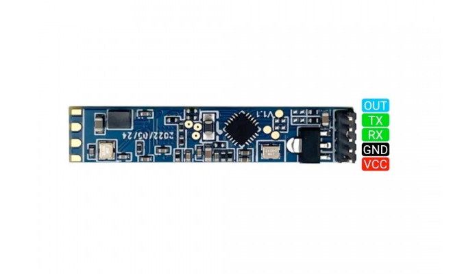
| Pin | Type | Description | Notes |
|---|---|---|---|
| VCC | Power | Power input | 5V DC |
| GND | Power | Ground connection | |
| TX | Communication | UART transmit | Sends data from sensor (connect to ESP32 RX) |
| RX | Communication | UART receive | Receives commands (connect to ESP32 TX) |
| OUT | Communication | Digital presence output | HIGH when presence detected (optional) |
Interface: UART (256000 baud) + Bluetooth LE
Technology: 24GHz FMCW radar with integrated BLE
Detection: Both stationary and moving human targets
Range: Up to 6 meters (improved from LD2410)
Field of View: ±60° detection angle
Bluetooth: BLE for wireless configuration (HiLink app)
Gates: Configurable distance gates (0.2m or 0.75m resolution)
Power: 5V DC, stable power required
Pin Spacing: 1.27mm (compact design)
Applications: Smart lighting, occupancy sensing, HVAC control, security systems
Wiring the LD2410B to ESP32
To interface the LD2410B with an ESP32 for human presence detection via UART:
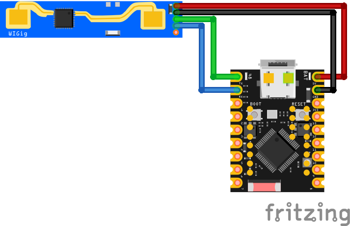
| LD2410B pin | ESP32 pin | Purpose |
|---|---|---|
| VCC | 5V | Power supply (5V) |
| GND | GND | Ground |
| TX | GPIO16 (RX2) | Sensor transmit to ESP32 receive |
| RX | GPIO17 (TX2) | Sensor receive from ESP32 transmit |
| OUT | GPIO18 | Digital presence output (optional) · optional |
UART2: Use UART2 on ESP32 (GPIO16/17 are default UART2 pins)
Baud Rate: 256000 bps - must match in firmware configuration
Power: Requires stable 5V supply (power even when using BLE)
TX/RX: Connect sensor TX to ESP32 RX, sensor RX to ESP32 TX
OUT Pin: Optional digital output goes HIGH on presence detection
Bluetooth Setup: Use HiLink/HLK Radar BLE app for wireless configuration
BLE vs UART: BLE and UART cannot operate simultaneously on most firmware
Workflow: Configure via BLE, then use UART for continuous operation
LD2410B code examples
// Requires library: "MyLD2410"
#if defined(ARDUINO_SAMD_NANO_33_IOT) || defined(ARDUINO_AVR_LEONARDO)
//ARDUINO_SAMD_NANO_33_IOT RX_PIN is D1, TX_PIN is D0
//ARDUINO_AVR_LEONARDO RX_PIN(RXI) is D0, TX_PIN(TXO) is D1
#define sensorSerial Serial1
#elif defined(ARDUINO_XIAO_ESP32C3) || defined(ARDUINO_XIAO_ESP32C6)
//RX_PIN is D7, TX_PIN is D6
#define sensorSerial Serial0
#elif defined(ESP32)
//Other ESP32 device - choose available GPIO pins
#define sensorSerial Serial1
#if defined(ARDUINO_ESP32S3_DEV)
#define RX_PIN 18
#define TX_PIN 17
#else
#define RX_PIN 16
#define TX_PIN 17
#endif
#else
#error "This sketch only works on ESP32, Arduino Nano 33IoT, and Arduino Leonardo (Pro-Micro)"
#endif

// User defines
// #define DEBUG_MODE
#define ENHANCED_MODE
#define SERIAL_BAUD_RATE 115200

//Change the communication baud rate here, if necessary
//#define LD2410_BAUD_RATE 256000
#include "MyLD2410.h"

#ifdef DEBUG_MODE
MyLD2410 sensor(sensorSerial, true);
#else
MyLD2410 sensor(sensorSerial);
#endif

unsigned long nextPrint = 0, printEvery = 1000;  // print every second

void printValue(const byte &val) {
  Serial.print(' ');
  Serial.print(val);
}

void printData() {
  Serial.print(sensor.statusString());
  if (sensor.presenceDetected()) {
    Serial.print(", distance: ");
    Serial.print(sensor.detectedDistance());
    Serial.print("cm");
  }
  Serial.println();
  if (sensor.movingTargetDetected()) {
    Serial.print(" MOVING    = ");
    Serial.print(sensor.movingTargetSignal());
    Serial.print("@");
    Serial.print(sensor.movingTargetDistance());
    Serial.print("cm ");
    if (sensor.inEnhancedMode()) {
      Serial.print("\n signals->[");
      sensor.getMovingSignals().forEach(printValue);
      Serial.print(" ] thresholds:[");
      sensor.getMovingThresholds().forEach(printValue);
      Serial.print(" ]");
    }
    Serial.println();
  }
  if (sensor.stationaryTargetDetected()) {
    Serial.print(" STATIONARY= ");
    Serial.print(sensor.stationaryTargetSignal());
    Serial.print("@");
    Serial.print(sensor.stationaryTargetDistance());
    Serial.print("cm ");
    if (sensor.inEnhancedMode()) {
      Serial.print("\n signals->[");
      sensor.getStationarySignals().forEach(printValue);
      Serial.print(" ] thresholds:[");
      sensor.getStationaryThresholds().forEach(printValue);
      Serial.print(" ]");
    }
    Serial.println();
  }

  if (sensor.inEnhancedMode() && (sensor.getFirmwareMajor() > 1)) {
    Serial.print("Light level: ");
    Serial.println(sensor.getLightLevel());
    Serial.print("Output level: ");
    Serial.println((sensor.getOutLevel()) ? "HIGH" : "LOW");
  }

  Serial.println();
}

void setup() {
  Serial.begin(SERIAL_BAUD_RATE);
#if defined(ARDUINO_XIAO_ESP32C3) || defined(ARDUINO_XIAO_ESP32C6) || defined(ARDUINO_SAMD_NANO_33_IOT) || defined(ARDUINO_AVR_LEONARDO)
  sensorSerial.begin(LD2410_BAUD_RATE);
#else
  sensorSerial.begin(LD2410_BAUD_RATE, SERIAL_8N1, RX_PIN, TX_PIN);
#endif
  delay(2000);
  Serial.println(__FILE__);
  if (!sensor.begin()) {
    Serial.println("Failed to communicate with the sensor.");
    while (true) {}
  }

#ifdef ENHANCED_MODE
  sensor.enhancedMode();
#else
  sensor.enhancedMode(false);
#endif

  delay(nextPrint);
}

void loop() {
  if ((sensor.check() == MyLD2410::Response::DATA) && (millis() > nextPrint)) {
    nextPrint = millis() + printEvery;
    printData();
  }
}
The LD2410B is fully compatible with the same Arduino code used for the LD2410 sensor. You can refer to the MyLD2410 library and use identical UART wiring and commands. No code changes are required aside from ensuring BLE is disabled or inactive during UART communication. See LD2410 Arduino Example for implementation details.
#include <stdio.h>
#include <string.h>
#include "freertos/FreeRTOS.h"
#include "freertos/task.h"
#include "driver/uart.h"

// LD2410B on UART2: radar TX -> GPIO16 (RX2), RX -> GPIO17 (TX2), 256000 baud
#define RADAR_UART UART_NUM_2
#define RADAR_RX_PIN 16
#define RADAR_TX_PIN 17

static const uint8_t FRAME_HEAD[4] = {0xF4, 0xF3, 0xF2, 0xF1};

void app_main(void)
{
    uart_config_t config = {
        .baud_rate = 256000,
        .data_bits = UART_DATA_8_BITS,
        .parity = UART_PARITY_DISABLE,
        .stop_bits = UART_STOP_BITS_1,
        .flow_ctrl = UART_HW_FLOWCTRL_DISABLE,
    };
    ESP_ERROR_CHECK(uart_param_config(RADAR_UART, &config));
    ESP_ERROR_CHECK(uart_set_pin(RADAR_UART, RADAR_TX_PIN, RADAR_RX_PIN,
                                 UART_PIN_NO_CHANGE, UART_PIN_NO_CHANGE));
    ESP_ERROR_CHECK(uart_driver_install(RADAR_UART, 1024, 0, 0, NULL, 0));

    uint8_t buf[64];
    int matched = 0;

    while (1) {
        uint8_t byte;
        if (uart_read_bytes(RADAR_UART, &byte, 1, pdMS_TO_TICKS(100)) != 1)
            continue;

        // Sync on the F4 F3 F2 F1 data-frame header
        if (matched < 4) {
            matched = (byte == FRAME_HEAD[matched]) ? matched + 1 : (byte == FRAME_HEAD[0]);
            continue;
        }

        // Read length (2 bytes, little-endian), then the payload + 4-byte tail
        uint8_t len_bytes[2];
        len_bytes[0] = byte;
        uart_read_bytes(RADAR_UART, &len_bytes[1], 1, pdMS_TO_TICKS(100));
        int length = len_bytes[0] | (len_bytes[1] << 8);
        matched = 0;
        if (length < 11 || length > (int)sizeof(buf))
            continue; // implausible - resync

        if (uart_read_bytes(RADAR_UART, buf, length + 4, pdMS_TO_TICKS(100)) != length + 4)
            continue;

        // Basic-mode report: [0]=0x02, [1]=0xAA, [2]=state, then little-endian values
        if (buf[0] != 0x02 || buf[1] != 0xAA)
            continue; // engineering-mode or config frame - ignore here

        uint8_t state = buf[2]; // 0 none, 1 moving, 2 still, 3 both
        int moving_cm = buf[3] | (buf[4] << 8);
        int still_cm = buf[6] | (buf[7] << 8);
        int detect_cm = buf[9] | (buf[10] << 8);

        static const char *STATES[] = {"no target", "moving", "still", "moving + still"};
        printf("%s | moving %d cm (energy %d) | still %d cm (energy %d) | detect %d cm\n",
               STATES[state & 0x03], moving_cm, buf[5], still_cm, buf[8], detect_cm);
    }
}
ESP-IDF has no component for the LD2410B, but the radar's continuous data stream is easy to parse directly: every report starts with the header F4 F3 F2 F1 followed by a little-endian length, a basic-mode payload (type 0x02, head 0xAA) carrying the target state (none/moving/still/both), the moving and still target distances in centimeters with their energy values, and the overall detection distance. The example syncs on the header, validates the type bytes and prints each report. Configuration commands (sensitivity, gate settings) use a separate FD FC FB FA frame format described in the vendor's protocol manual.
uart:
  id: uart_bus
  tx_pin: GPIO17
  rx_pin: GPIO16
  baud_rate: 256000

ld2410:
  uart_id: uart_bus

binary_sensor:
  - platform: ld2410
    has_target:
      name: "Presence Detected"
    has_moving_target:
      name: "Moving Target Detected"
    has_still_target:
      name: "Still Target Detected"

sensor:
  - platform: ld2410
    moving_distance:
      name: "Moving Distance"
    still_distance:
      name: "Still Distance"
    moving_energy:
      name: "Moving Energy"
    still_energy:
      name: "Still Energy"
    detection_distance:
      name: "Detection Distance"

text_sensor:
  - platform: ld2410
    version:
      name: "LD2410 Firmware Version"
    mac_address:
      name: "LD2410 MAC Address"
This uses ESPHome's core ld2410 component over UART2 at the radar's fixed 256000 baud. Older examples carried their own esphome: block with the removed platform: ESP32 syntax - the snippet now contains only the sensor-specific parts. Presence, moving/still target states and their distances/energies all become entities, and the component also exposes configuration entities (timeout, gate sensitivities) if you add them.
[env:esp32dev]
platform = espressif32
board = esp32dev
framework = arduino
monitor_speed = 115200
lib_deps =
iavorvel/MyLD2410 @ ^1.2.8#include <Arduino.h>
#if defined(ARDUINO_SAMD_NANO_33_IOT) || defined(ARDUINO_AVR_LEONARDO)
//ARDUINO_SAMD_NANO_33_IOT RX_PIN is D1, TX_PIN is D0
//ARDUINO_AVR_LEONARDO RX_PIN(RXI) is D0, TX_PIN(TXO) is D1
#define sensorSerial Serial1
#elif defined(ARDUINO_XIAO_ESP32C3) || defined(ARDUINO_XIAO_ESP32C6)
//RX_PIN is D7, TX_PIN is D6
#define sensorSerial Serial0
#elif defined(ESP32)
//Other ESP32 device - choose available GPIO pins
#define sensorSerial Serial1
#if defined(ARDUINO_ESP32S3_DEV)
#define RX_PIN 18
#define TX_PIN 17
#else
#define RX_PIN 16
#define TX_PIN 17
#endif
#else
#error "This sketch only works on ESP32, Arduino Nano 33IoT, and Arduino Leonardo (Pro-Micro)"
#endif
// User defines
// #define DEBUG_MODE
#define ENHANCED_MODE
#define SERIAL_BAUD_RATE 115200
//Change the communication baud rate here, if necessary
//#define LD2410_BAUD_RATE 256000
#include "MyLD2410.h"
#ifdef DEBUG_MODE
MyLD2410 sensor(sensorSerial, true);
#else
MyLD2410 sensor(sensorSerial);
#endif
unsigned long nextPrint = 0, printEvery = 1000; // print every second
void printValue(const byte &val) {
Serial.print(' ');
Serial.print(val);
}
void printData() {
Serial.print(sensor.statusString());
if (sensor.presenceDetected()) {
Serial.print(", distance: ");
Serial.print(sensor.detectedDistance());
Serial.print("cm");
}
Serial.println();
if (sensor.movingTargetDetected()) {
Serial.print(" MOVING = ");
Serial.print(sensor.movingTargetSignal());
Serial.print("@");
Serial.print(sensor.movingTargetDistance());
Serial.print("cm ");
if (sensor.inEnhancedMode()) {
Serial.print("\n signals->[");
sensor.getMovingSignals().forEach(printValue);
Serial.print(" ] thresholds:[");
sensor.getMovingThresholds().forEach(printValue);
Serial.print(" ]");
}
Serial.println();
}
if (sensor.stationaryTargetDetected()) {
Serial.print(" STATIONARY= ");
Serial.print(sensor.stationaryTargetSignal());
Serial.print("@");
Serial.print(sensor.stationaryTargetDistance());
Serial.print("cm ");
if (sensor.inEnhancedMode()) {
Serial.print("\n signals->[");
sensor.getStationarySignals().forEach(printValue);
Serial.print(" ] thresholds:[");
sensor.getStationaryThresholds().forEach(printValue);
Serial.print(" ]");
}
Serial.println();
}
if (sensor.inEnhancedMode() && (sensor.getFirmwareMajor() > 1)) {
Serial.print("Light level: ");
Serial.println(sensor.getLightLevel());
Serial.print("Output level: ");
Serial.println((sensor.getOutLevel()) ? "HIGH" : "LOW");
}
Serial.println();
}
void setup() {
Serial.begin(SERIAL_BAUD_RATE);
#if defined(ARDUINO_XIAO_ESP32C3) || defined(ARDUINO_XIAO_ESP32C6) || defined(ARDUINO_SAMD_NANO_33_IOT) || defined(ARDUINO_AVR_LEONARDO)
sensorSerial.begin(LD2410_BAUD_RATE);
#else
sensorSerial.begin(LD2410_BAUD_RATE, SERIAL_8N1, RX_PIN, TX_PIN);
#endif
delay(2000);
Serial.println(__FILE__);
if (!sensor.begin()) {
Serial.println("Failed to communicate with the sensor.");
while (true) {}
}
#ifdef ENHANCED_MODE
sensor.enhancedMode();
#else
sensor.enhancedMode(false);
#endif
delay(nextPrint);
}
void loop() {
if ((sensor.check() == MyLD2410::Response::DATA) && (millis() > nextPrint)) {
nextPrint = millis() + printEvery;
printData();
}
}The LD2410B is fully compatible with the same MyLD2410 PlatformIO library and example code used for the LD2410. You can use identical UART wiring (TX=17, RX=16) and no code changes are necessary to support LD2410B functionality. The sensor will operate normally over UART as long as Bluetooth is not actively connected. Refer to the LD2410 PlatformIO Example for a complete implementation using the PlatformIO environment.
from machine import UART
import time

# Initialize UART2: TX=17, RX=16, baud rate 256000
uart = UART(2, baudrate=256000, tx=17, rx=16)

# Function to read and print data from LD2410
def read_ld2410():
    while True:
        if uart.any():
            data = uart.read()
            if data:
                print(data)
        time.sleep(0.1)

read_ld2410()
LD2410B supports the same UART communication protocol as the original LD2410, making it fully compatible with existing MicroPython code. You can use the same UART setup (TX=17, RX=16, baudrate=256000) and raw data reading scripts. Note that BLE should not be active while using UART. For the base script and driver link, see the MicroPython section of the LD2410 documentation.
LD2410B specifications
About the LD2410B
The LD2410B takes the base LD2410 radar - same 24GHz FMCW chip, same roughly 5-to-6-meter range in 0.2 m or 0.75 m gates, same ±60 degree field of view - and adds Bluetooth Low Energy so the sensor can be tuned from Hi-Link’s HLKRadarTool phone app instead of over a wired serial connection. That matters once a sensor is mounted inside a ceiling fixture or behind a wall plate: reconfiguring gate sensitivities over UART means pulling it back out, while BLE reaches it in place, provided you stay within the app’s roughly 4-meter Bluetooth range.
Detection capability is otherwise unchanged from the plain LD2410 - the radar hardware and 256000-baud UART protocol are identical, and the same MyLD2410 library and ESPHome ld2410 component (which exposes a Bluetooth on/off switch) work without modification. The trade-off is the same 1.27 mm pin pitch as the base model, which is fiddly on a standard breadboard; the LD2410C offers the same Bluetooth configuration on 2.54 mm header pins instead.
Buy the LD2410B over the plain LD2410 only if wireless configuration is worth the modest price premium - for a bench project with the sensor sitting on a breadboard within reach of a USB cable, the base model does everything the B does except let you tune it over BLE.
LD2410B troubleshooting
Bluetooth Not Detected
›
Issue: The sensor does not appear in the BLE scanner app during setup.
Ensure the module is powered and not actively communicating via UART. BLE is typically disabled during UART operation. Power cycle the sensor without a UART connection and scan again.
No Data Over UART
›
Issue: ESP32 receives no UART data from the sensor.
Confirm correct wiring of TX/RX and check that BLE mode is not interfering. BLE and UART should not operate simultaneously in some firmware versions.
Detection Delay
›
Issue: Presence detection is delayed or inconsistent.
Use the Bluetooth configuration app to adjust sensitivity gates and energy thresholds. Ensure no large obstacles block the radar field.
Cannot Access Configuration
›
Issue: Neither BLE nor UART configuration is working.
Reset the device using a hardware reset if available, or power cycle while holding a configuration button (if present). Consult the datasheet for boot behavior.
Where to buy the LD2410B

Resources
Similar sensors


