
Ai-Thinker RD-01 24GHz mmWave Radar Sensor
The Ai-Thinker RD-01 is a high-sensitivity 24GHz radar sensor capable of detecting human presence and motion. It communicates via UART and is ideal for smart home and security applications.

RD-01 pinout
The RD-01 has 5 pins: 3.3V power, GND, UART TX/RX, and a required CHIP_EN enable pin.
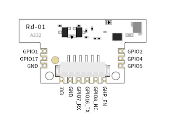
| Pin | Type | Description | Notes |
|---|---|---|---|
| 3V3 | Power | Power input (3.3V ONLY). Do not exceed 3.6V. | 3.3V only - exceeding voltage will damage the module. |
| GND | Power | Ground reference. Must be shared with ESP32. | Common ground essential for signal integrity. |
| TX | UART | UART transmit pin. Outputs presence and motion data. | Connect to ESP32 RX pin (e.g., GPIO 16). 3.3V logic. |
| RX | UART | UART receive pin. Accepts configuration commands. | Connect to ESP32 TX pin (e.g., GPIO 17). |
| CHIP_EN | Control | Chip enable (active high). MUST be pulled HIGH for operation. | REQUIRED: Tie to 3.3V or control with GPIO. Cannot be left floating. |
24GHz FMCW mmWave radar technology
Detection range: up to 5 meters
Field of view: ±60° horizontal
3.3V ONLY - do not use 5V power or logic
CHIP_EN must be HIGH - cannot be left floating
Integrated Wi-Fi and BLE capabilities
Detects both moving and stationary targets
Wiring the RD-01 to ESP32
To interface the RD-01 with an ESP32, connect 3V3 to 3.3V power, GND to ground, TX to GPIO 16 (RX2), RX to GPIO 17 (TX2), and CHIP_EN to 3.3V or a GPIO pin.
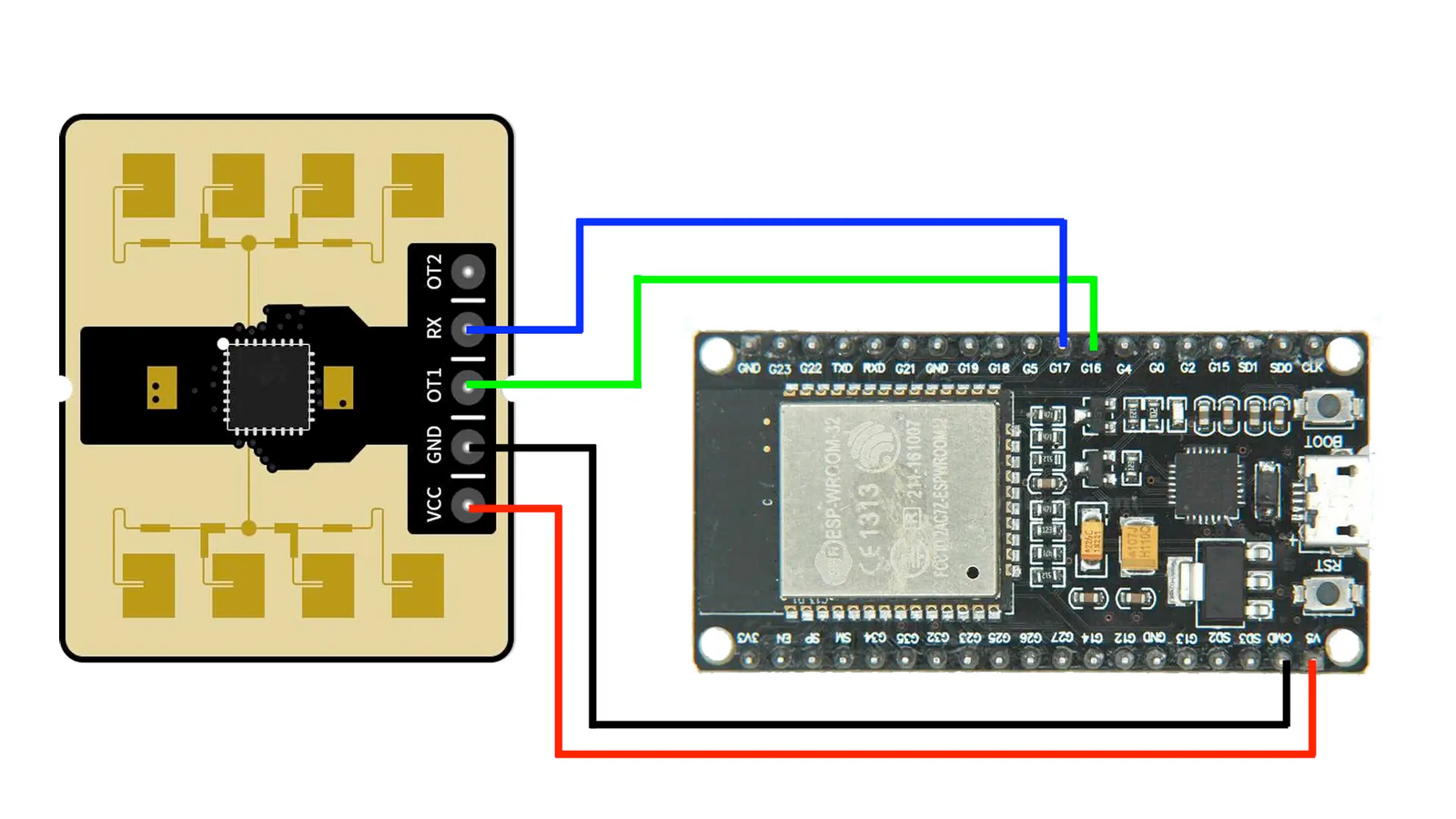
| RD-01 pin | ESP32 pin | Purpose |
|---|---|---|
| 3V3 (red) | 3.3V | Power supply (3.3V ONLY). Do not use 5V. |
| GND (black) | GND | Ground connection. Must be common with ESP32. |
| TX (green) | GPIO 16 (RX2) | Radar transmits data to ESP32. |
| RX (blue) | GPIO 17 (TX2) | ESP32 sends configuration commands to radar. |
| CHIP_EN (yellow) | 3.3V or GPIO | Enable pin. MUST be HIGH. Tie to 3.3V or use GPIO for control. |
CRITICAL: Use only 3.3V power - 5V will damage the module
CRITICAL: CHIP_EN must be pulled HIGH - never leave floating
UART baud rate: 115200 bps (8N1 format)
Use UART2 on ESP32 (GPIO 16/17) to avoid USB serial conflicts
All logic levels are 3.3V - directly compatible with ESP32
Mount sensor securely - vibrations affect detection
Clear line of sight required in detection zone
Similar to LD series radar - reference LD2410 examples
For GPIO control of CHIP_EN: HIGH=enabled, LOW=disabled/reset
RD-01 code examples
// Rd-01: module TX -> GPIO16 (RX2), RX -> GPIO17 (TX2), 115200 baud
HardwareSerial radar(2);

void setup() {
  Serial.begin(115200);
  radar.begin(115200, SERIAL_8N1, 16, 17);
  Serial.println("Rd-01 frame monitor");
}

void loop() {
  while (radar.available()) {
    uint8_t b = radar.read();
    if (b < 0x10) Serial.print("0");
    Serial.print(b, HEX);
    Serial.print(" ");
  }
  Serial.println();
  delay(200);
}
There is no established Arduino library for the Rd-01, so this example prints its UART stream as hex - decode it with Ai-Thinker's Rd-01 serial protocol manual. The module is based on the same radar family as the HLK-LD2410.
#include <stdio.h>
#include "freertos/FreeRTOS.h"
#include "freertos/task.h"
#include "driver/uart.h"

// Rd-01 on UART2: module TX -> GPIO16 (RX2), RX -> GPIO17 (TX2), 115200 baud
#define RADAR_UART UART_NUM_2

void app_main(void)
{
    uart_config_t config = {
        .baud_rate = 115200,
        .data_bits = UART_DATA_8_BITS,
        .parity = UART_PARITY_DISABLE,
        .stop_bits = UART_STOP_BITS_1,
        .flow_ctrl = UART_HW_FLOWCTRL_DISABLE,
    };
    ESP_ERROR_CHECK(uart_param_config(RADAR_UART, &config));
    ESP_ERROR_CHECK(uart_set_pin(RADAR_UART, 17, 16, UART_PIN_NO_CHANGE, UART_PIN_NO_CHANGE));
    ESP_ERROR_CHECK(uart_driver_install(RADAR_UART, 1024, 0, 0, NULL, 0));

    uint8_t buf[64];
    while (1) {
        int len = uart_read_bytes(RADAR_UART, buf, sizeof(buf), pdMS_TO_TICKS(200));
        if (len > 0) {
            for (int i = 0; i < len; i++)
                printf("%02X ", buf[i]);
            printf("\n");
        }
    }
}
There is no established library for the Rd-01, so this example reads its UART stream (115200 baud on UART2) and prints each burst as hex - decode it with the frame tables in Ai-Thinker's Rd-01 serial protocol manual. The module is based on the same radar family as the HLK-LD2410.
[env:esp32dev]
platform = espressif32
board = esp32dev
framework = arduino
monitor_speed = 115200#include <Arduino.h>
// Rd-01: module TX -> GPIO16 (RX2), RX -> GPIO17 (TX2), 115200 baud
HardwareSerial radar(2);
void setup() {
Serial.begin(115200);
radar.begin(115200, SERIAL_8N1, 16, 17);
Serial.println("Rd-01 frame monitor");
}
void loop() {
while (radar.available()) {
uint8_t b = radar.read();
if (b < 0x10) Serial.print("0");
Serial.print(b, HEX);
Serial.print(" ");
}
Serial.println();
delay(200);
}Same hex frame monitor as the Arduino example, built with PlatformIO. Decode the frames with Ai-Thinker's Rd-01 serial protocol manual. The module is based on the same radar family as the HLK-LD2410.
from machine import UART
import time

# Rd-01: module TX -> GPIO16 (RX2), RX -> GPIO17 (TX2), 115200 baud
uart = UART(2, baudrate=115200, tx=17, rx=16)

while True:
    data = uart.read()
    if data:
        print(" ".join("{:02X}".format(b) for b in data))
    time.sleep(0.2)
There is no established library for the Rd-01, so this example reads its UART stream (115200 baud on UART2) and prints each burst as hex - decode it with the frame tables in Ai-Thinker's Rd-01 serial protocol manual. The module is based on the same radar family as the HLK-LD2410.
RD-01 specifications
About the RD-01
The Ai-Thinker RD-01 pairs a 24GHz FMCW radar chip (ICLEGEND MICRO’s S3KM111L, detecting moving, subtly moving and stationary targets out to about 5 meters across a ±60 degree field) with Ai-Thinker’s own BL602 co-processor, which adds 802.11b/g/n Wi-Fi and Bluetooth 5.0 on the same board. That is unusual for this family - every Hi-Link and Seeed sensor here talks UART only, but the RD-01’s BL602 side means the module could report presence over Wi-Fi or BLE without an ESP32 in the loop at all, even though the wiring and code on this page use it the same way as the rest: as a 115200-baud UART presence sensor.
Two things to get right when wiring it: CHIP_EN must be pulled high, tied to 3.3V or driven from a GPIO, or the module never starts, and the 1.25mm pin pitch, even tighter than the LD2410’s 1.27mm, usually needs an adapter board or careful hand soldering to reach a breadboard. Power is 3.0-3.6V only; there is no 5V tolerance to fall back on.
ESPHome has no RD-01 component as of late 2026, so Home Assistant integration means writing a UART parser by hand or leaning on the vendor’s own tools - the native-ESPHome MR24HPC1 or LD2410 is the easier route if that matters more than the RD-01’s built-in wireless silicon. Do not confuse it with the newer RD-03D, which is Ai-Thinker’s multi-target tracking radar built around a different chip and antenna design entirely.
RD-01 troubleshooting
No Data Received
›
Issue: The ESP32 receives no data from the sensor.
Ensure correct wiring: verify that TX and RX lines are properly connected, and confirm that the UART baud rate is set to 115200 bps. Also, ensure that the sensor is powered with a stable 3.3V supply and that the CHIP_EN pin is set to high.
Presence Not Detected
›
Issue: The sensor does not detect presence even when someone is in range.
Check the sensor's field of view and ensure there are no obstructions. Verify that the sensor's configuration parameters are set correctly for the desired detection range and sensitivity.
Intermittent Detection
›
Issue: Sensor intermittently detects presence or fails to maintain detection.
Ensure that the sensor is securely mounted and not subject to vibrations. Check for sources of interference in the environment that may affect radar performance.
UART Initialization Fails
›
Issue: UART component in ESPHome reports failure to initialize.
Verify that the UART pins specified in the configuration match the physical connections. Ensure that no other devices are using the same UART bus, and that the baud rate is correctly set to 115200 bps.
Where to buy the RD-01
Resources
Similar sensors


