
RDM6300 RFID Reader Module
The RDM6300 is a simple and reliable 125kHz RFID reader module suitable for a wide range of identification and access control applications. Its straightforward UART interface ensures easy integration into any project requiring RFID capabilities.

RDM6300 pinout
The RDM6300 has 4 pins: VCC, GND, TX (for data output), and RX (rarely used).
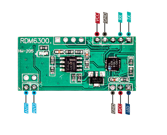
| Pin | Type | Description | Notes |
|---|---|---|---|
| VCC | Power | Power supply input (3.3V to 5V). Flexible voltage range. | Both 3.3V and 5V compatible. |
| GND | Power | Ground connection. Connect to system ground. | |
| TX | UART | UART transmit data. Sends 125kHz RFID tag UID to microcontroller. | Connect to ESP32 RX pin. Main data output. |
| RX | UART | UART receive data. Bidirectional communication (rarely used). | Optional - most applications only use TX. |
125kHz low-frequency RFID reader
Compatible with EM4100 protocol tags
UART output at 9600 baud (default)
Reading distance: typically 3-8cm
Automatic tag detection - no polling required
Outputs unique tag ID when card detected
Wiring the RDM6300 to ESP32
To interface the RDM6300 with an ESP32, connect VCC to 3.3V or 5V, GND to ground, and TX to an ESP32 RX pin (GPIO 16) to receive tag UID data.
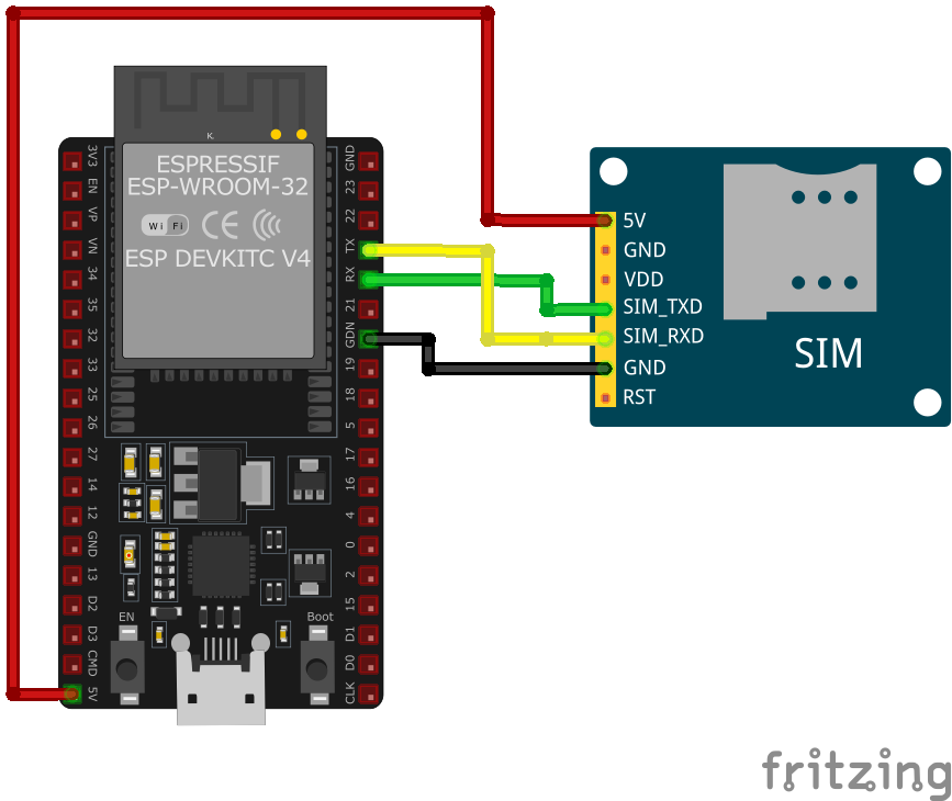
| RDM6300 pin | ESP32 pin | Purpose |
|---|---|---|
| VCC | 3.3V or 5V | Power supply. Use 3.3V or 5V depending on your setup. |
| GND | GND | Ground connection. |
| TX | GPIO 16 (RX2) | Reader transmits tag UID to ESP32. |
| RX | Optional GPIO 17 | Bidirectional communication (rarely needed). · optional |
UART baud rate: 9600 bps (default, can be changed on some modules)
Use UART2 on ESP32 (GPIO 16/17) for hardware serial
Data format: 14-byte ASCII string containing tag UID
Automatic tag detection - continuously outputs when tag present
Reading distance: 3-8cm depending on tag size
Compatible tags: EM4100, EM4102, and similar 125kHz cards/tags
RX pin usually not needed - reader operates in output-only mode
Module includes coil antenna - ensure proper orientation
For access control: store authorized UIDs and compare readings
RDM6300 code examples
// The RDM6300 sends each tag as a 14-byte ASCII frame over UART (9600 baud):
// STX(0x02) + 10 hex chars (2 version + 8 tag ID) + 2 checksum chars + ETX(0x03)

HardwareSerial rfid(2); // UART2: reader TX -> GPIO16 (RX2); TX to the reader is not needed

void setup() {
    Serial.begin(115200);
    rfid.begin(9600, SERIAL_8N1, 16, -1); // RX only
    Serial.println("RDM6300 initialized. Waiting for RFID tags...");
}

void loop() {
    if (rfid.available() && rfid.read() == 0x02) { // frame start
        char frame[13];
        int got = rfid.readBytes(frame, 13); // 10 data + 2 checksum + ETX
        if (got == 13 && frame[12] == 0x03) {
            char tagHex[9];
            memcpy(tagHex, frame + 2, 8); // skip the 2 version chars
            tagHex[8] = '\0';
            unsigned long tagId = strtoul(tagHex, NULL, 16);

            Serial.print("Tag detected: ");
            Serial.print(tagHex);
            Serial.print(" (decimal ");
            Serial.print(tagId);
            Serial.println(")");
        }
    }
    delay(50);
}
The RDM6300 only transmits, so a single UART connection is enough: reader TX to GPIO16 (UART2 RX). Each detected tag arrives as a 14-byte ASCII frame - start byte 0x02, ten hex characters (two version + eight tag ID), two checksum characters and end byte 0x03. The sketch syncs on the start byte, extracts the 8-character tag ID and prints it both as hex and as the decimal number often printed on the key fob.
// The RDM6300 sends each tag as a 14-byte ASCII frame over UART (9600 baud):
// STX(0x02) + 10 hex chars (2 version + 8 tag ID) + 2 checksum chars + ETX(0x03)
#include <stdio.h>
#include <stdlib.h>
#include <string.h>
#include "freertos/FreeRTOS.h"
#include "freertos/task.h"
#include "driver/uart.h"

#define RX_PIN 16 // Reader TX -> GPIO16; TX to the reader is not needed
#define UART_PORT UART_NUM_1

void init_uart(void) {
    uart_config_t uart_config = {
        .baud_rate = 9600,
        .data_bits = UART_DATA_8_BITS,
        .parity = UART_PARITY_DISABLE,
        .stop_bits = UART_STOP_BITS_1,
        .flow_ctrl = UART_HW_FLOWCTRL_DISABLE
    };
    uart_param_config(UART_PORT, &uart_config);
    uart_set_pin(UART_PORT, UART_PIN_NO_CHANGE, RX_PIN, UART_PIN_NO_CHANGE, UART_PIN_NO_CHANGE);
    uart_driver_install(UART_PORT, 1024, 0, 0, NULL, 0);
}

void app_main(void) {
    init_uart();
    printf("RDM6300 initialized. Waiting for tags...\n");

    uint8_t byte;
    uint8_t frame[13];

    while (true) {
        // Sync on the 0x02 start byte
        if (uart_read_bytes(UART_PORT, &byte, 1, pdMS_TO_TICKS(100)) == 1 && byte == 0x02) {
            int got = uart_read_bytes(UART_PORT, frame, 13, pdMS_TO_TICKS(100));
            if (got == 13 && frame[12] == 0x03) {
                char tag_hex[9];
                memcpy(tag_hex, frame + 2, 8); // skip the 2 version chars
                tag_hex[8] = '\0';
                unsigned long tag_id = strtoul(tag_hex, NULL, 16);
                printf("Tag detected: %s (decimal %lu)\n", tag_hex, tag_id);
            }
        }
    }
}
This ESP-IDF code configures a UART interface to communicate with the RDM6300 module. The init_uart function initializes the UART peripheral, and the app_main function continuously reads incoming tag data. The tag UID is logged to the console, making it suitable for integration into access control or identification systems.
uart:
  rx_pin: GPIO16  # reader TX -> GPIO16; TX to the reader is not needed
  baud_rate: 9600

rdm6300:
  on_tag:
    - logger.log:
        format: "Tag scanned: %u"
        args: ['x']

binary_sensor:
  - platform: rdm6300
    uid: 7616525  # replace with your tag's ID (see the log line above)
    name: "RDM6300 Known Tag"
ESPHome has native RDM6300 support: the rdm6300 hub parses the reader's 125 kHz tag frames from UART (only RX is needed - reader TX to GPIO16). on_tag fires for every scan with the numeric tag ID, and a binary_sensor matches one specific tag. The old custom-platform example no longer works - that component was removed from ESPHome in 2025.
[env:rdm6300]
platform = espressif32
board = esp32dev
framework = arduino
monitor_speed = 115200#include <HardwareSerial.h>
HardwareSerial rfid(1);
void setup() {
Serial.begin(115200);
rfid.begin(9600, SERIAL_8N1, 16, 17); // RX, TX
Serial.println("RDM6300 initialized. Waiting for tags...");
}
void loop() {
if (rfid.available() > 0) {
String tag = "";
while (rfid.available() > 0) {
char c = rfid.read();
tag += c;
}
Serial.print("Tag detected: ");
Serial.println(tag);
}
delay(500);
}This PlatformIO code initializes a UART interface to communicate with the RDM6300 module. Incoming RFID tag data is read and displayed on the Serial Monitor. The loop function continuously checks for tag data and handles its output, making it suitable for quick prototyping or integration into other systems.
from machine import UART, Pin
import time

# Initialize UART
uart = UART(2, baudrate=9600, tx=17, rx=16)

print("RDM6300 initialized. Waiting for tags...")

while True:
    if uart.any():
        tag = uart.read().decode('utf-8')
        print("Tag detected:", tag)
    time.sleep(0.5)
This MicroPython code sets up UART communication with the RDM6300 RFID module. The script continuously listens for incoming RFID tag data and prints the UID to the console. The simplicity of the code makes it ideal for quick prototyping or integration into identification projects.
RDM6300 specifications
About the RDM6300
The RDM6300 is a 125 kHz low-frequency RFID reader, a different technology entirely from 13.56 MHz parts like the RC522 or PN532 - the frequency, the tags, and the whole ecosystem are unrelated, so an RDM6300 cannot read a MIFARE card and a MIFARE reader cannot read the fobs this module is built for. It targets EM4100/EM4102-compatible tags, the plain unencrypted fobs and cards common on older access-control and asset-tracking systems, and reports each tag over a single UART TX line at a fixed 9600 baud with no trigger or query needed from the host.
Each detected tag arrives as a 14-byte ASCII frame - a start byte, ten hex characters (a 2-character version field plus the 8-character tag ID), two checksum characters, and an end byte - simple enough to parse without a library, though ESPHome and a handful of Arduino libraries handle it directly. The module is read-only: it can report a tag’s ID but cannot write to one, even though EM4100-compatible tags exist in writable variants (like T5577) that other 125 kHz readers can program - a limitation confirmed by hobbyists who have had to build custom firmware specifically to add write support.
That simplicity is also the security weakness: a bare tag ID transmits in the clear with no encryption or challenge-response, and 125 kHz cards are trivially cloned with a cheap writer, so an RDM6300-based system is access convenience, not real security. At around 4 dollars it is a cheap way to add badge-style identification to a project, but if a design needs the encrypted, sector-keyed MIFARE ecosystem instead, the RC522 is the 13.56 MHz equivalent - just note that the two are not interchangeable at the tag level.
RDM6300 troubleshooting
Module Fails to Power On
›
Issue: The RDM6300 module does not power up or respond to commands.
Possible causes include insufficient power supply, incorrect wiring, or faulty hardware.
Solution: Ensure the module is connected to a stable power source within the recommended voltage range of 5V. Verify that all connections are secure and correctly configured. If the problem persists, consider testing the module with a different power source or replacing it.
Communication Interface Not Working
›
Issue: The module fails to communicate with the microcontroller over the chosen interface (typically UART).
Possible causes include incorrect wiring, improper interface selection, or incompatible voltage levels.
Solution: Double-check the wiring to ensure correct connections for UART communication. For UART, verify the TX and RX lines are properly connected. Ensure that the microcontroller's UART interface is enabled and configured correctly.
Unable to Read Tags
›
Issue: The module initializes correctly but fails to read RFID tags.
Possible causes include incorrect antenna orientation, insufficient power supply, or interference from nearby electronic devices.
Solution: Ensure the module's antenna is properly oriented and positioned near the tags. Verify that the power supply provides adequate current for the module's operation. Keep the module away from sources of electromagnetic interference.
Inconsistent Tag Detection
›
Issue: The module detects tags intermittently or with delays.
Possible causes include low-quality tags, environmental interference, or firmware issues.
Solution: Test with different tags to rule out tag quality issues. Ensure the operating environment is free from strong electromagnetic interference. Update the module's firmware to the latest version to benefit from bug fixes and improvements.
Library or Software Issues
›
Issue: The module operates erratically or produces errors during operation.
Possible causes include outdated or incompatible libraries, incorrect initialization, or software bugs.
Solution: Ensure that the latest version of the RDM6300 library is installed and compatible with your development environment. Review the initialization code to confirm that the module is set up correctly. Consult the module's documentation and community forums for guidance on proper usage.
Where to buy the RDM6300


