ESP32 PN532 NFC Module
Overview
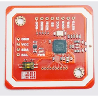
The PN532 NFC module provides a powerful and flexible platform for integrating NFC and RFID capabilities into your projects. Its multi-protocol support and versatile interfaces make it suitable for various use cases, including access control, contactless payment, and data exchange.
About PN532 NFC Module
The PN532 is a widely used NFC and RFID module, offering reliable wireless data exchange for various applications.
⚡ Key Features
- Multi-Protocol Support – Works with ISO/IEC 14443 Type A & B cards and NFC peer-to-peer communication.
- Flexible Interfaces – Supports I2C, SPI, and UART, ensuring easy integration.
- Versatile Applications – Ideal for access control, contactless payments, smart authentication, and data exchange.
- Compact & Efficient – Low power consumption with a high-performance NFC controller.
Where to Buy


Prices are subject to change. We earn from qualifying purchases as an Amazon Associate.
Technical Specifications
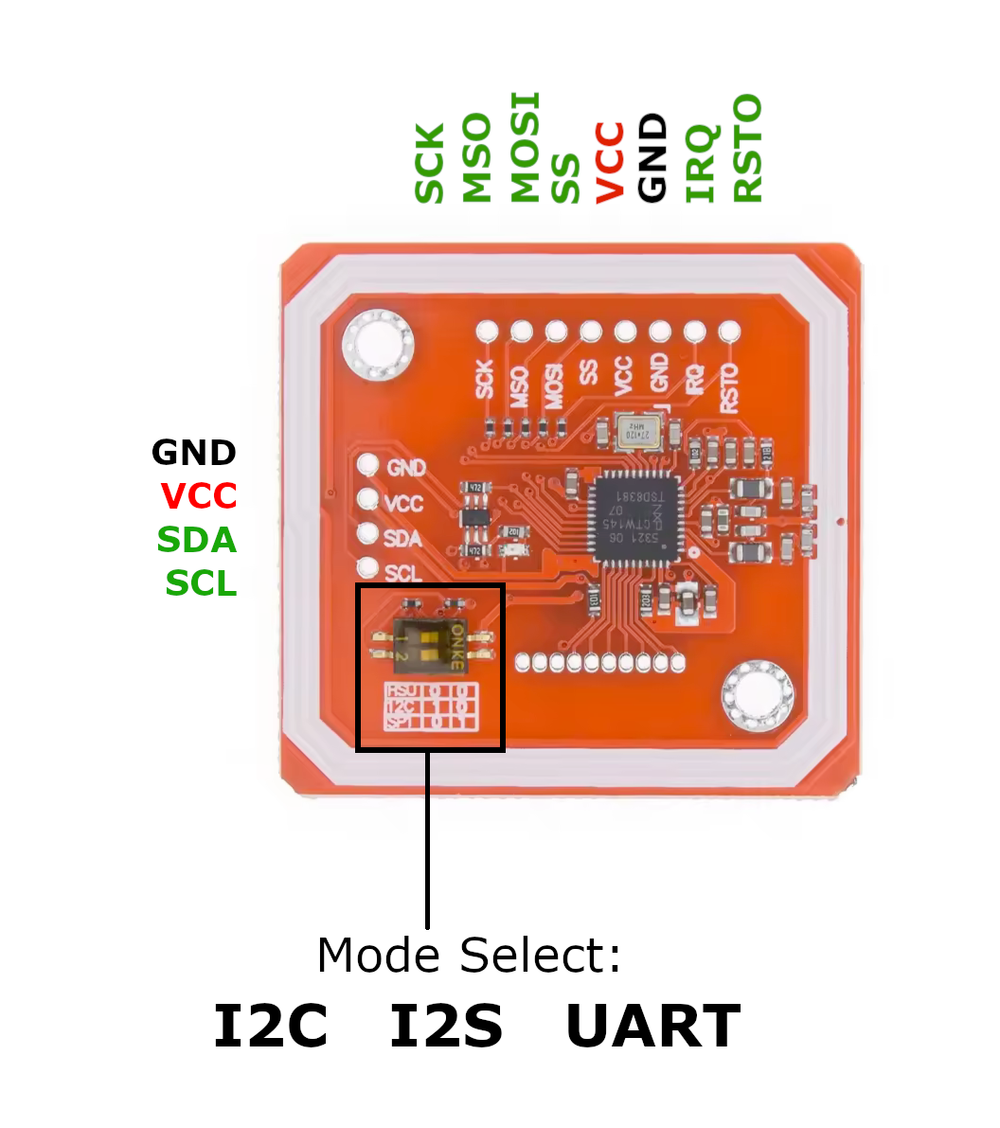
Pinout Configuration
The VCC pin is used to supply power to the sensor, and it typically requires 3.3V or 5V (refer to the datasheet for specific voltage requirements). The GND pin is the ground connection and must be connected to the ground of your ESP32.
PN532 Communication Modes
The PN532 module is a versatile NFC controller that supports multiple communication protocols, including I²C, SPI, and HSU (High-Speed UART). Depending on your requirements, you can select the desired communication mode by setting the small switches to the appropriate positions.I²C Mode
| Protocol | Switch 1 | Switch 2 |
|---|---|---|
| I2C | ✅ | ❌ |
- VCC: Power supply (3.3V or 5V)
- GND: Ground
- SDA: I²C Data Line
- SCL: I²C Clock Line
- IRQ: Optional (for interrupts)
- RSTO: Optional (reset)
SPI Mode
| Protocol | Switch 1 | Switch 2 |
|---|---|---|
| I2C | ❌ | ✅ |
- VCC: Power supply (3.3V or 5V)
- GND: Ground
- MISO: Master In Slave Out
- MOSI: Master Out Slave In
- SCK: Serial Clock
- SS (NSS): Slave Select
- IRQ: Optional (for interrupts)
- RSTO: Optional (reset)
HSU Mode (High-Speed UART)
| Protocol | Switch 1 | Switch 2 |
|---|---|---|
| I2C | ❌ | ❌ |
💡 When using HSU (High-Speed UART) mode, the SDA (I²C Data) and SCL (I²C Clock) pins are repurposed as UART TX and RX.
- VCC: Power supply (3.3V or 5V)
- GND: Ground
- SDA (TX): Transmit Data (to MCU RX)
- SCL (RXD): Receive Data (to MCU TX)
- IRQ: Optional (for interrupts)
- RSTO: Optional (reset)
PN532 Pins Required For Different Protocols
| PN532 Pin | I²C Mode | SPI Mode | HSU Mode (UART) |
|---|---|---|---|
| VCC | ✅ | ✅ | ✅ |
| GND | ✅ | ✅ | ✅ |
| SDA | ✅ (I²C Data) | ❌ | ✅ (TX - To ESP32 RX) |
| SCL | ✅ (I²C Clock) | ❌ | ✅ (RX - To ESP32 TX) |
| MISO | ❌ | ✅ | ❌ |
| MOSI | ❌ | ✅ | ❌ |
| SCK | ❌ | ✅ | ❌ |
| SS (NSS) | ❌ | ✅ | ❌ |
| IRQ | Optional | Optional | Optional |
| RSTO | Optional | Optional | Optional |
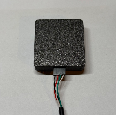
3D Printed Enclosure
We offer a variety of enclosures for the ESP32 C3 Super Mini, available in different colors and configurations – with or without header pins, and more! You can also choose between a hexagon-patterned lid for improved heat dispersion ❄️ or a solid lid for a sleek finish.
Each enclosure is carefully designed and tested to ensure perfect fit and functionality. Made with premium materials for durability and aesthetics.
Wiring with ESP32
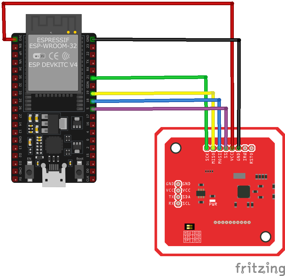
SPI Protocol Wiring with ESP32
In SPI (Serial Peripheral Interface) mode, the PN532 NFC module communicates with the ESP32 using a fast, synchronous data exchange method. This mode is ideal for high-speed applications requiring stable communication.
Connections:
- VCC → 3.3V (ESP32)
- GND → GND (ESP32)
- MISO → GPIO19 (ESP32 MISO)
- MOSI → GPIO23 (ESP32 MOSI)
- SCK → GPIO18 (ESP32 SCK)
- SS (NSS) → GPIO5 (ESP32 CS/SS)
- IRQ (Optional) → GPIO4 (ESP32 IRQ)
- RSTO (Optional) → GPIO21 (ESP32 Reset)
Key Features of SPI Mode:
- ✅ Faster communication compared to I²C.
- ✅ More stable data transfer for high-speed NFC applications.
- ✅ Uses dedicated SPI pins for efficient hardware support.
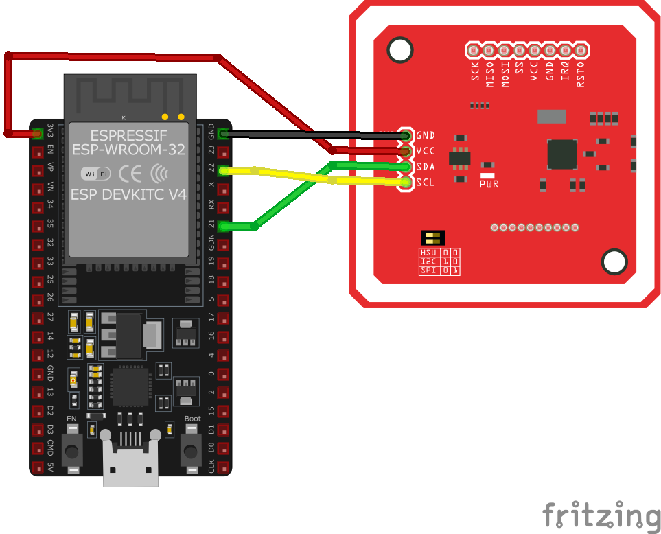
I2C Protocol Wiring with ESP32
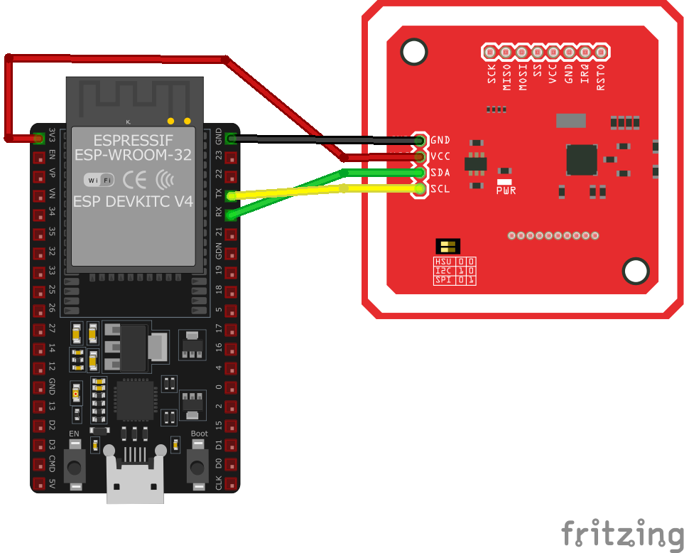
In I²C (Inter-Integrated Circuit) mode, the PN532 NFC module communicates with the ESP32 using a two-wire communication method. This mode is simple and requires fewer connections compared to SPI.
Connections:
- VCC → 3.3V (ESP32)
- GND → GND (ESP32)
- SDA → GPIO21 (ESP32 SDA)
- SCL → GPIO22 (ESP32 SCL)
- IRQ (Optional) → GPIO4 (ESP32 IRQ)
- RSTO (Optional) → GPIO5 (ESP32 Reset)
Key Features of I²C Mode:
- ✅ Uses only two data lines (SDA & SCL), making it ideal for minimal wiring.
- ✅ Multiple devices can share the same I²C bus.
- ✅ Simpler setup compared to SPI.
HSU (High-Speed UART) Wiring with ESP32
In HSU (High-Speed UART) mode, the PN532 NFC module communicates with the ESP32 using a serial UART interface. This mode is useful for applications requiring a simple and widely supported communication method.
Connections:
- VCC → 3.3V (ESP32)
- GND → GND (ESP32)
- SDA (HSU TX) → GPIO16 (ESP32 RX)
- SCL (HSU RX) → GPIO17 (ESP32 TX)
- IRQ (Optional) → GPIO4 (ESP32 IRQ)
- RSTO (Optional) → GPIO5 (ESP32 Reset)
Key Features of HSU (UART) Mode:
- ✅ Uses standard UART communication, widely supported by microcontrollers.
- ✅ Simple wiring, requiring only TX, RX, VCC, and GND.
- ✅ High-speed data transfer, suitable for real-time NFC applications.
Troubleshooting Guide
Common Issues
⚡ Module Fails to Power On
Issue: The PN532 module does not power up or respond to commands.
Possible causes include insufficient power supply, incorrect wiring, or faulty hardware.
Solution: Ensure the module is connected to a stable power source within the recommended voltage range of 3.3V to 5V. Verify that all connections are secure and correctly configured. If the problem persists, consider testing the module with a different power source or replacing it.
🔄 Communication Interface Not Working
Issue: The module fails to communicate with the microcontroller over the chosen interface (I2C, SPI, or UART).
Possible causes include incorrect wiring, improper interface selection, or incompatible voltage levels.
Solution: Double-check the wiring to ensure correct connections for the chosen interface. For I2C, ensure that the SDA and SCL lines are properly connected, and for SPI, verify the MOSI, MISO, SCK, and SS lines. If using I2C, ensure that pull-up resistors are present on the SDA and SCL lines.
📡 Unable to Read Tags
Issue: The module initializes correctly but fails to read NFC or RFID tags.
Possible causes include incorrect antenna orientation, insufficient power supply, or interference from nearby electronic devices.
Solution: Ensure the module's antenna is properly oriented and positioned near the tags. Verify that the power supply provides adequate current for the module's operation. Keep the module away from sources of electromagnetic interference.
⚠️ Inconsistent Tag Detection
Issue: The module detects tags intermittently or with delays.
Possible causes include low-quality tags, environmental interference, or firmware issues.
Solution: Test with different tags to rule out tag quality issues. Ensure the operating environment is free from strong electromagnetic interference. Update the module's firmware to the latest version to benefit from bug fixes and improvements.
🖥️ Library or Software Issues
Issue: The module operates erratically or produces errors during operation.
Possible causes include outdated or incompatible libraries, incorrect initialization, or software bugs.
Solution: Ensure that the latest version of the PN532 library is installed and compatible with your development environment. Review the initialization code to confirm that the module is set up correctly. Consult the module's documentation and community forums for guidance on proper usage.
Debugging Tips
🔍 Serial Monitor
Use the Serial Monitor to check for error messages and verify the sensor's output. Add debug prints in your code to track the sensor's state.
⚡ Voltage Checks
Use a multimeter to verify voltage levels and check for continuity in your connections. Ensure the power supply is stable and within the sensor's requirements.
Additional Resources
Code Examples
Arduino Example
#include <Wire.h>
#include <Adafruit_PN532.h>

#define SDA_PIN 21
#define SCL_PIN 22
Adafruit_PN532 nfc(SDA_PIN, SCL_PIN);

void setup() {
    Serial.begin(115200);
    Serial.println("Initializing PN532...");
    nfc.begin();

    uint32_t version = nfc.getFirmwareVersion();
    if (!version) {
        Serial.println("Didn't find PN532 board");
        while (1);
    }

    nfc.SAMConfig();
    Serial.println("PN532 initialized!");
}

void loop() {
    Serial.println("Waiting for NFC tag...");
    uint8_t success;
    uint8_t uid[] = {0};
    uint8_t uidLength;

    success = nfc.readPassiveTargetID(PN532_MIFARE_ISO14443A, uid, &uidLength);
    if (success) {
        Serial.print("Found NFC tag with UID: ");
        for (uint8_t i = 0; i < uidLength; i++) {
            Serial.print(uid[i], HEX);
            Serial.print(" ");
        }
        Serial.println();
    }
    delay(1000);
}Required Library #
To use this code, ensure you have installed the Adafruit PN532 library. You can install it via the Arduino Library Manager:
- Open Arduino IDE.
- Navigate to Sketch → Include Library → Manage Libraries.
- Search for 'Adafruit PN532' and install it.
The setup function initializes the module, and the firmware version is retrieved for verification. In the loop, the module continuously scans for NFC tags and prints the UID of any detected tag. Additional features, such as writing to tags or handling other NFC modes, can be implemented as needed.
ESP-IDF Example
#include <stdio.h>
#include <stdlib.h>
#include <esp_log.h>

#include "freertos/FreeRTOS.h"
#include "freertos/task.h"

#include "sdkconfig.h"
#include "pn532_driver_i2c.h"
#include "pn532_driver_hsu.h"
#include "pn532.h"


// select ONLY ONE interface for the PN532
#define PN532_MODE_I2C 1
#define PN532_MODE_HSU 0
#define PN532_MODE_SPI 0

#if PN532_MODE_I2C

// I2C mode needs only SDA, SCL and IRQ pins. RESET pin will be used if valid.
// IRQ pin can be used in polling mode or in interrupt mode. Use menuconfig to select mode.
#define SCL_PIN    (0)
#define SDA_PIN    (1)
#define RESET_PIN  (-1)
#define IRQ_PIN    (3)

#elif PN532_MODE_HSU

// HSU mode needs only RX/TX pins. RESET pin will be used if valid.
#define RESET_PIN      (-1)
#define IRQ_PIN        (-1)
#define HSU_HOST_RX    (4)
#define HSU_HOST_TX    (5)
#define HSU_UART_PORT  UART_NUM_1
#define HSU_BAUD_RATE  (921600)

#elif PN532_MODE_SPI

#error SPI is not implemented

#endif

static const char *TAG = "ntag_read";

void app_main()
{
    pn532_io_t pn532_io;
    esp_err_t err;

    printf("APP MAIN
");

#if 0
    // Enable DEBUG logging
    esp_log_level_set("PN532", ESP_LOG_DEBUG);
    esp_log_level_set("pn532_driver", ESP_LOG_DEBUG);
    esp_log_level_set("pn532_driver_i2c", ESP_LOG_DEBUG);
    esp_log_level_set("pn532_driver_hsu", ESP_LOG_DEBUG);
    esp_log_level_set("i2c.master", ESP_LOG_DEBUG);
#endif

    vTaskDelay(1000 / portTICK_PERIOD_MS);

#if PN532_MODE_I2C

    ESP_LOGI(TAG, "init PN532 in I2C mode");
    ESP_ERROR_CHECK(pn532_new_driver_i2c(SDA_PIN, SCL_PIN, RESET_PIN, IRQ_PIN, 0, &pn532_io));

#elif PN532_MODE_HSU

    ESP_LOGI(TAG, "init PN532 in HSU mode");
    ESP_ERROR_CHECK(pn532_new_driver_hsu(HSU_HOST_RX,
                                         HSU_HOST_TX,
                                         RESET_PIN,
                                         IRQ_PIN,
                                         HSU_UART_PORT,
                                         HSU_BAUD_RATE,
                                         &pn532_io));

#endif

    do {
        err = pn532_init(&pn532_io);
        if (err != ESP_OK) {
            ESP_LOGW(TAG, "failed to initialize PN532");
            pn532_release(&pn532_io);
            vTaskDelay(1000 / portTICK_PERIOD_MS);
        }
    } while(err != ESP_OK);

    ESP_LOGI(TAG, "get firmware version");
    uint32_t version_data = 0;
    do {
        err = pn532_get_firmware_version(&pn532_io, &version_data);
        if (ESP_OK != err) {
            ESP_LOGI(TAG, "Didn't find PN53x board");
            pn532_reset(&pn532_io);
            vTaskDelay(1000 / portTICK_PERIOD_MS);
        }
    } while (ESP_OK != err);

    // Log firmware infos
    ESP_LOGI(TAG, "Found chip PN5%x", (unsigned int)(version_data >> 24) & 0xFF);
    ESP_LOGI(TAG, "Firmware ver. %d.%d", (int)(version_data >> 16) & 0xFF, (int)(version_data >> 8) & 0xFF);

    ESP_LOGI(TAG, "Waiting for an ISO14443A Card ...");
    while (1)
    {
        uint8_t uid[] = {0, 0, 0, 0, 0, 0, 0}; // Buffer to store the returned UID
        uint8_t uid_length;                     // Length of the UID (4 or 7 bytes depending on ISO14443A card type)

        // Wait for an ISO14443A type cards (Mifare, etc.).  When one is found
        // 'uid' will be populated with the UID, and uid_length will indicate
        // if the uid is 4 bytes (Mifare Classic) or 7 bytes (Mifare Ultralight)
        err = pn532_read_passive_target_id(&pn532_io, PN532_BRTY_ISO14443A_106KBPS, uid, &uid_length, 0);

        if (ESP_OK == err)
        {
            // Display some basic information about the card
            ESP_LOGI(TAG, "
Found an ISO14443A card");
            ESP_LOGI(TAG, "UID Length: %d bytes", uid_length);
            ESP_LOGI(TAG, "UID Value:");
            ESP_LOG_BUFFER_HEX_LEVEL(TAG, uid, uid_length, ESP_LOG_INFO);

            err = pn532_in_list_passive_target(&pn532_io);
            if (err != ESP_OK) {
                ESP_LOGI(TAG, "Failed to inList passive target");
                continue;
            }

            NTAG2XX_MODEL ntag_model = NTAG2XX_UNKNOWN;
            err = ntag2xx_get_model(&pn532_io, &ntag_model);
            if (err != ESP_OK)
                continue;

            int page_max;
            switch (ntag_model) {
                case NTAG2XX_NTAG213:
                    page_max = 45;
                    ESP_LOGI(TAG, "found NTAG213 target (or maybe NTAG203)");
                    break;

                case NTAG2XX_NTAG215:
                    page_max = 135;
                    ESP_LOGI(TAG, "found NTAG215 target");
                    break;

                case NTAG2XX_NTAG216:
                    page_max = 231;
                    ESP_LOGI(TAG, "found NTAG216 target");
                    break;

                default:
                    ESP_LOGI(TAG, "Found unknown NTAG target!");
                    continue;
            }

            for(int page=0; page < page_max; page+=4) {
                uint8_t buf[16];
                err = ntag2xx_read_page(&pn532_io, page, buf, 16);
                if (err == ESP_OK) {
                    ESP_LOG_BUFFER_HEXDUMP(TAG, buf, 16, ESP_LOG_INFO);
                }
                else {
                    ESP_LOGI(TAG, "Failed to read page %d", page);
                    break;
                }
            }
            vTaskDelay(1000 / portTICK_PERIOD_MS);
        }
    }
}Library Requirement #
To compile this code, install the PN532 ESP-IDF driver from:
🔗 Garag/esp-idf-pn532
Required headers:
pn532_driver_i2c.hpn532_driver_hsu.hpn532.h
Key Features #
- Interface Selection: Supports I2C (SDA: GPIO1, SCL: GPIO0) or HSU (UART1, 921600 baud).
- PN532 Initialization: Reads the firmware version.
- NFC Tag Detection: Scans for ISO14443A tags and logs the UID.
- NTAG2XX Reading: Identifies NTAG213, NTAG215, or NTAG216 and dumps memory pages.
- Logging: Uses
ESP_LOGI()for debugging.
The program continuously scans for new NFC tags and logs their details.
ESPHome Example
# Choose one - SPI or I2C!

# Over SPI
pn532_spi:
  cs_pin: D3
  update_interval: 1s


binary_sensor:
  - platform: pn532
    uid: 74-10-37-94
    name: "PN532 NFC Tag"

# Over I2C
pn532_i2c:
  update_interval: 1s

binary_sensor:
  - platform: pn532
    uid: 74-10-37-94
    name: "PN532 NFC Tag"
This ESPHome configuration sets up the PN532 NFC module to detect NFC tags. It supports either SPI or I2C, but you must choose only one.
Configuration Options #
SPI Mode
pn532_spi:
  cs_pin: D3
update_interval: 1s- Uses SPI with a chip-select pin (
D3). - Scans for NFC tags every 1 second.
- Uses SPI with a chip-select pin (
I2C Mode
pn532_i2c:
update_interval: 1s- Uses I2C (SDA/SCL defined in ESPHome settings).
- Scans for NFC tags every 1 second.
NFC Tag Detection #
binary_sensor:
  - platform: pn532
    uid: 74-10-37-94
name: "PN532 NFC Tag"- Detects an NFC tag with a specific UID (
74-10-37-94). - Appears as a binary sensor in ESPHome.
Important: Choose One Interface #
- If using SPI, configure
pn532_spi. - If using I2C, configure
pn532_i2c. - Do not enable both at the same time.
For more details, check the official ESPHome PN532 documentation:
🔗 ESPHome PN532 Component
PlatformIO Example
platformio.ini
[env:pn532]
platform = espressif32
board = esp32dev
framework = arduino
monitor_speed = 115200
PlatformIO Example Code
#include <Wire.h>
#include <Adafruit_PN532.h>

Adafruit_PN532 nfc(21, 22);

void setup() {
    Serial.begin(115200);
    nfc.begin();

    if (!nfc.getFirmwareVersion()) {
        Serial.println("Failed to find PN532!");
        while (1);
    }
    nfc.SAMConfig();
    Serial.println("Waiting for NFC tag...");
}

void loop() {
    uint8_t uid[7];
    uint8_t uidLength;
    if (nfc.readPassiveTargetID(PN532_MIFARE_ISO14443A, uid, &uidLength)) {
        Serial.print("Found NFC tag with UID: ");
        for (uint8_t i = 0; i < uidLength; i++) {
            Serial.print(uid[i], HEX);
            Serial.print(" ");
        }
        Serial.println();
    }
    delay(1000);
}MicroPython Example
from machine import I2C, Pin
import time
from pn532_i2c import PN532_I2C

# Initialize I2C
i2c = I2C(1, scl=Pin(22), sda=Pin(21))
pn532 = PN532_I2C(i2c, debug=False)

pn532.SAM_configuration()

while True:
    print("Waiting for NFC tag...")
    uid = pn532.read_passive_target()
    if uid:
        print("Found NFC tag with UID:", [hex(i) for i in uid])
time.sleep(1)Conclusion
The ESP32 PN532 NFC Module is a powerful NFC sensor that offers excellent performance and reliability. With support for multiple development platforms including Arduino, ESP-IDF, ESPHome, PlatformIO, and MicroPython, it's a versatile choice for your IoT projects.
For optimal performance, ensure proper wiring and follow the recommended configuration for your chosen development platform.
Always verify power supply requirements and pin connections before powering up your project to avoid potential damage.
