
Elecrow CrowPanel Advance 5.0 (ESP32-P4)
5" 800x480 HMI touchscreen built on the ESP32-P4 with 32MB PSRAM - Wi-Fi 6 comes from an onboard ESP32-C6, and a socket takes optional Zigbee, LoRa or nRF24 radio modules.

Elecrow CrowPanel Advance 5.0 (ESP32-P4) Pinout
47 pins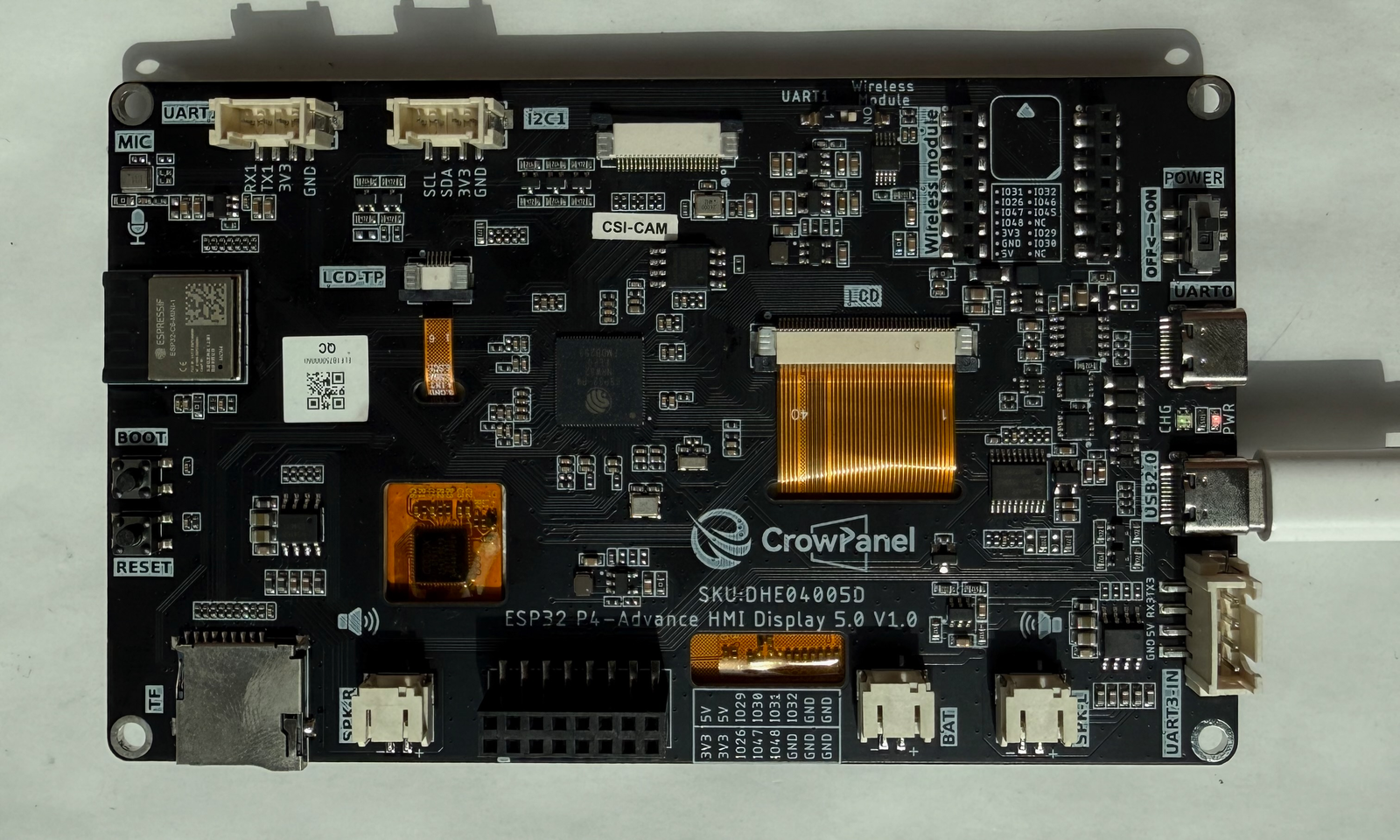
| Pin | GPIO | Labels | Status | Capabilities | Notes |
|---|---|---|---|---|---|
| 1 | 2 | IO2LCD_DE | safe | - | Internal - RGB panel data enable |
| 2 | 3 | IO3LCD_PCLK | safe | - | Internal - RGB panel pixel clock (16MHz) |
| 3 | 4 | IO4LCD_B7 | safe | - | Internal - RGB panel data |
| 4 | 5 | IO5LCD_B6 | safe | - | Internal - RGB panel data |
| 5 | 6 | IO6LCD_B5 | safe | - | Internal - RGB panel data |
| 6 | 7 | IO7LCD_B4 | safe | - | Internal - RGB panel data |
| 7 | 8 | IO8LCD_B3 | safe | - | Internal - RGB panel data |
| 8 | 9 | IO9LCD_G7 | safe | - | Internal - RGB panel data |
| 9 | 10 | IO10LCD_G6 | safe | - | Internal - RGB panel data |
| 10 | 11 | IO11LCD_G5 | safe | - | Internal - RGB panel data |
| 11 | 12 | IO12LCD_G4 | safe | - | Internal - RGB panel data |
| 12 | 13 | IO13LCD_G3 | safe | - | Internal - RGB panel data |
| 13 | 14 | IO14LCD_G2 | safe | - | Internal - RGB panel data |
| 14 | 15 | IO15LCD_R7 | safe | - | Internal - RGB panel data |
| 15 | 16 | IO16LCD_R6 | safe | - | Internal - RGB panel data |
| 16 | 17 | IO17LCD_R5 | safe | - | Internal - RGB panel data |
| 17 | 18 | IO18LCD_R4 | safe | - | Internal - RGB panel data |
| 18 | 19 | IO19LCD_R3 | safe | - | Internal - RGB panel data |
| 19 | 21 | IO21I2S_LRCK | safe | - | Internal I2S word clock to the NS4168 speaker amplifiers |
| 20 | 22 | IO22I2S_SCLK | safe | - | Internal I2S bit clock to the NS4168 speaker amplifiers |
| 21 | 23 | IO23I2S_SDOUT | safe | - | Internal I2S data out to the NS4168 speaker amplifiers |
| 22 | 24 | IO24MIC_CLK | uart | - | Internal - PDM microphone clock |
| 23 | 25 | IO25MIC_DATA | uart | - | Internal - PDM microphone data |
| 24 | 26 | IO26SPI_CLK | safe | spi | On the GPIO header - shared SPI clock for the display init interface and the wireless module socket |
| 25 | 27 | IO27UART3_TX | uart | uart | UART3-IN port - the port also accepts 5V/2A power input |
| 26 | 28 | IO28UART3_RX | uart | uart | UART3-IN port - the port also accepts 5V/2A power input |
| 27 | 29 | IO29GPIO_HDR | safe | - | Free GPIO on the 2x8 header - also routed to the wireless module socket |
| 28 | 30 | IO30GPIO_HDR | safe | - | Free GPIO on the 2x8 header - also the wireless module socket's BUSY line when a module is fitted |
| 29 | 31 | IO31GPIO_HDR | uart | uart | Free GPIO on the 2x8 header - also wired to the wireless module socket as UART2 TX |
| 30 | 32 | IO32C6_RST | safe | - | Reset line for the onboard ESP32-C6 radio (ESP-Hosted) - also routed to the GPIO header and module socket (UART2 RX), but leave it to the radio driver |
| 31 | 36 | IO36TP_RST | strapping | - | Internal - GT911 touch controller reset |
| 32 | 37 | IO37TXD0 | strapping | uart | UART0 - flashing and logs via the CH340K USB-C port |
| 33 | 38 | IO38RXD0 | strapping | uart | UART0 - flashing and logs via the CH340K USB-C port |
| 34 | 39 | IO39SD_D0 | safe | - | microSD slot - data 0 (card select is hard-wired to GND) |
| 35 | 42 | IO42TP_INT | safe | - | Internal - GT911 touch controller interrupt |
| 36 | 43 | IO43SD_SCK | safe | - | microSD slot - clock |
| 37 | 44 | IO44SD_CMD | safe | - | microSD slot - command |
| 38 | 45 | IO45SDA | safe | i2c | Shared I2C bus - Crowtail I2C port, GT911 touch and the STC8 backlight controller (0x2F); add devices, don't repurpose |
| 39 | 46 | IO46SCL | safe | i2c | Shared I2C bus - same bus as IO45 |
| 40 | 47 | IO47UART1_TXSPI_MOSI | uart | uart · spi | Crowtail UART1 port and GPIO header, shared with the wireless module socket SPI - a DIP switch selects which is active |
| 41 | 48 | IO48UART1_RX | uart | uart · spi | Crowtail UART1 port and GPIO header, shared with the wireless module socket SPI - a DIP switch selects which is active |
| 42 | 49 | IO49C6_SDIO_D3 | safe | - | Reserved - SDIO data to the onboard ESP32-C6 radio (ESP-Hosted link), not usable as GPIO |
| 43 | 50 | IO50C6_SDIO_D2 | safe | - | Reserved - SDIO data to the onboard ESP32-C6 radio, not usable as GPIO |
| 44 | 51 | IO51C6_SDIO_D1 | safe | - | Reserved - SDIO data to the onboard ESP32-C6 radio, not usable as GPIO |
| 45 | 52 | IO52C6_SDIO_D0 | safe | - | Reserved - SDIO data to the onboard ESP32-C6 radio, not usable as GPIO |
| 46 | 53 | IO53C6_SDIO_CLK | safe | - | Reserved - SDIO clock to the onboard ESP32-C6 radio, not usable as GPIO |
| 47 | 54 | IO54C6_SDIO_CMD | safe | - | Reserved - SDIO command to the onboard ESP32-C6 radio, not usable as GPIO |
Start with these
42 pins with no boot or system involvementFreely assignable - no strapping, flash, USB or JTAG duties. Ideal first picks for buttons, sensors and LEDs.
Fine - with a little care
3 pins · 2 things to knowIO36 Strapping pin; part of boot-mode selection (with GPIO35) and controls ROM-message printing to UART0. Strapping
Sampled at reset for boot mode and log output; driving it at boot can change the boot mode or silence/enable ROM logs. Free after reset.
IO37IO38 Strapping pin; participates in chip boot-mode control (see ESP32-P4 TRM, Chip Boot Control). Strapping
Sampled at reset as a boot-mode strap; avoid holding it at a fixed level during boot unless intentionally configuring boot mode. Free after reset.
- IO37Strapping pin; participates in chip boot-mode control (see ESP32-P4 TRM, Chip Boot Control).
- IO38Strapping pin; participates in chip boot-mode control (see ESP32-P4 TRM, Chip Boot Control).
Only if you know the tricks
2 pins · 1 thing to knowIO24IO25 USB Serial/JTAG differential data pair, connected to the on-chip controller by default USB
Enabled as USB by default (used for flashing and console); using it as GPIO requires disabling/reconfiguring the USB Serial/JTAG function.
- IO24USB Serial/JTAG D- line; connected to the on-chip USB Serial/JTAG controller by default.
- IO25USB Serial/JTAG D+ line; connected to the on-chip USB Serial/JTAG controller by default.
All 47 pins on the Elecrow CrowPanel Advance 5.0 (ESP32-P4) are usable GPIO.
Peripheral wiring is straightforward: I²C is mapped to SDA on GPIO45 and SCL on GPIO46.
3 of the exposed pins carry boot-time or system duties on the ESP32-P4 (IO36, IO37 and IO38) - check the guidance above before wiring anything to them. IO2, IO3, IO4, IO5 and 38 more are free of any such role - the safest first picks.
Pinout notes Most of the P4's pins are spoken for by the display: the 800x480 panel runs on a 16-bit RGB565 parallel bus (IO4-IO19 data, DE on IO2, PCLK on IO3, HSYNC/VSYNC…
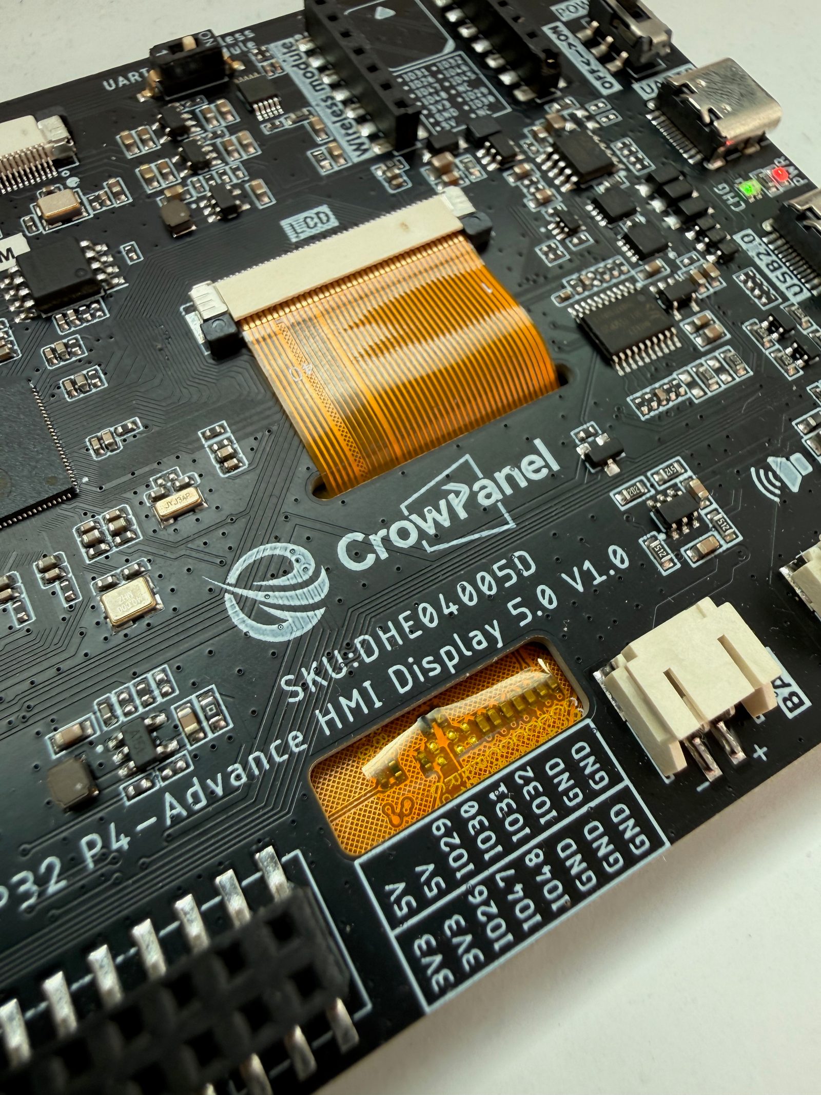
Most of the P4's pins are spoken for by the display: the 800x480 panel runs on a 16-bit RGB565 parallel bus (IO4-IO19 data, DE on IO2, PCLK on IO3, HSYNC/VSYNC on IO40/IO41). User I/O comes out through the ports instead: a Crowtail I2C port on IO45/IO46, a Crowtail UART1 port on IO47/IO48, a UART3-IN port on IO27/IO28 that doubles as a 5V/2A power input, and a 2x8 GPIO header carrying 3V3/5V rails plus IO26, IO29, IO30, IO31, IO32, IO47 and IO48 - of which only IO29, IO30 and IO31 are truly free general-purpose pins.
The I2C bus on IO45/IO46 is shared with the GT911 touch controller and the STC8 housekeeping MCU (address 0x2F) that controls the backlight - add devices to it, don't repurpose the pins. IO26/IO47/IO48 are likewise shared with the wireless module socket's SPI bus, selected by a DIP switch on the back: module mode and UART1 mode are mutually exclusive. The socket also routes the I2C bus and IO29-IO32, so header pins stop being free once a radio module is plugged in.
The onboard ESP32-C6 radio occupies IO49-IO54 as a dedicated SDIO link plus IO32 for reset - those pins are not available for your own use. The microSD slot sits on IO39/IO43/IO44 (card select is hard-wired), audio I2S is on IO21-IO23 and the PDM mic on IO24/IO25. UART0 flashing and logs go through the CH340K USB-C port.
Getting started
flash your first firmware in ~2 minutesBoard: ESP32P4 Dev Module USB CDC On Boot: Enabled Flash Size: 16MB (128Mb) PSRAM: QSPI PSRAM Partition Scheme: 16M Flash (3MB APP/9.9MB FATFS) Upload Speed: 921600
// toggle GPIO2 - wire an LED and resistor to it
void setup() {
  pinMode(2, OUTPUT);
}
void loop() {
  digitalWrite(2, HIGH); delay(500);
  digitalWrite(2, LOW);  delay(500);
}[env:elecrow-crowpanel-advance-5-esp32-p4]
platform = https://github.com/pioarduino/platform-espressif32/releases/download/stable/platform-espressif32.zip
board = esp32dev
framework = arduino
monitor_speed = 115200
upload_speed = 921600
board_build.arduino.memory_type = qio_qspi
build_flags = -DBOARD_HAS_PSRAMesp32dev - or type it after board =.esp32:
board: esp32dev
variant: esp32p4
framework:
type: esp-idf
psram:
mode: quad
speed: 80MHz
# blink - GPIO2
output:
- platform: gpio
pin: 2
id: led_out
light:
- platform: binary
name: "LED"
output: led_outesp32dev (same ids as PlatformIO).esptool.py --chip esp32p4 --port /dev/ttyACM0 \
--baud 921600 write_flash 0x2000 firmware.bin--port = your /dev/tty* (macOS/Linux) or COMx (Windows).Good to know
board-specific quirks worth 60 secondsUSB-C hosts decide whether anything is plugged in via the CC1/CC2 pins: a device must pull each to ground through a 5.1 kΩ resistor, and on the CrowPanel's USB 2.0 Device port those pulldowns appear to be missing. A spec-strict host - a Mac's USB-C port, notably - sees no pulldown, concludes nothing is attached, and never starts enumeration. VBUS still flows, so the board powers up and runs normally while staying…
USB-C hosts decide whether anything is plugged in via the CC1/CC2 pins: a device must pull each to ground through a 5.1 kΩ resistor, and on the CrowPanel's USB 2.0 Device port those pulldowns appear to be missing. A spec-strict host - a Mac's USB-C port, notably - sees no pulldown, concludes nothing is attached, and never starts enumeration. VBUS still flows, so the board powers up and runs normally while staying completely absent from the USB tree: no serial port, nothing in system_profiler SPUSBDataType. No driver can fix this, because the computer never saw a device. Legacy USB-A ports predate CC negotiation entirely - they just power the bus and enumerate whatever responds - so a USB-A to USB-C cable (through a hub or dock if your machine is C-only) makes the port work fine. Once connected, this port is the P4's built-in USB-Serial-JTAG: a standard driverless CDC device, so idf.py flash monitor gets flashing and the console on one cable, no CH34x driver needed.
When any USB device fails to show up, check enumeration first (system_profiler SPUSBDataType on macOS, lsusb on Linux). If it enumerated, it's a driver or permission problem; if it didn't, it's electrical - cable, CC resistors or power - and installing drivers is wasted motion. An empty /dev looks identical in both cases, which is exactly the trap.
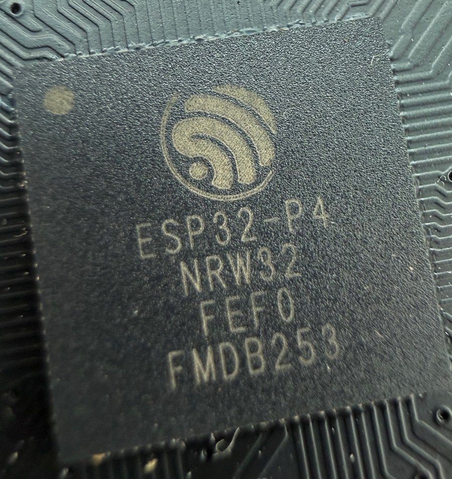
The P4 talks to an ESP32-C6-MINI-1 over a dedicated SDIO link (IO49-IO54, reset on IO32) running ESP-Hosted firmware. In ESPHome this is the esp32_hosted component; in ESP-IDF and Arduino the hosted driver makes Wi-Fi look native. The C6 ships pre-programmed at the factory - per Elecrow's own wiki, it can't be reprogrammed directly through the P4. Some users report Wi-Fi dropping after a few minutes on the stock…
The P4 talks to an ESP32-C6-MINI-1 over a dedicated SDIO link (IO49-IO54, reset on IO32) running ESP-Hosted firmware. In ESPHome this is the esp32_hosted component; in ESP-IDF and Arduino the hosted driver makes Wi-Fi look native. The C6 ships pre-programmed at the factory - per Elecrow's own wiki, it can't be reprogrammed directly through the P4. Some users report Wi-Fi dropping after a few minutes on the stock ESP-Hosted firmware (v2.3.0), needing a power cycle to recover; the UART pads for a direct fix aren't populated on the board, though a community-built OTA workaround exists.
If Wi-Fi is flaky or the board resets when the link comes up, drop sdio_frequency from the default 40MHz to 10-20MHz - Elecrow's own ESPHome example runs the link at 10MHz for stability.
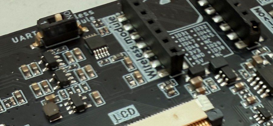
Like the rest of the Advance series, there's a socket on the back for optional radio modules - ESP32-H2 (Zigbee/Thread), LoRa, nRF2401 or Wi-Fi HaLow. The socket's SPI bus (IO26/IO47/IO48) shares pins with the Crowtail UART1 port, and a DIP switch selects which one is wired up. If UART1 (or a Crowtail sensor on it) has gone dead, check the function DIP switch first - in module mode those pins belong to the…
Like the rest of the Advance series, there's a socket on the back for optional radio modules - ESP32-H2 (Zigbee/Thread), LoRa, nRF2401 or Wi-Fi HaLow. The socket's SPI bus (IO26/IO47/IO48) shares pins with the Crowtail UART1 port, and a DIP switch selects which one is wired up.
If UART1 (or a Crowtail sensor on it) has gone dead, check the function DIP switch first - in module mode those pins belong to the socket.
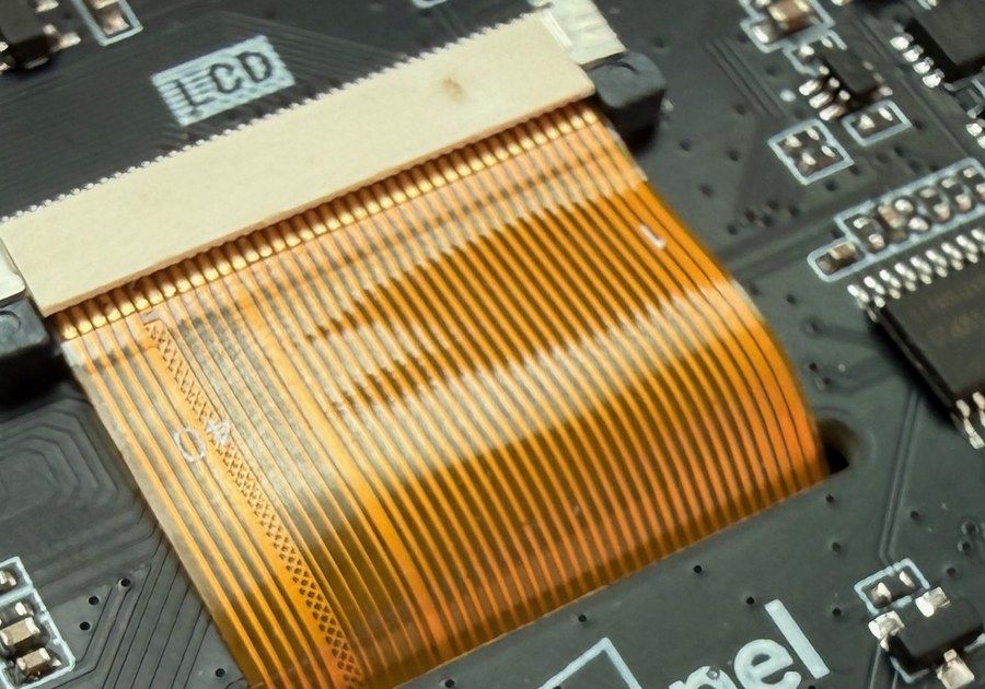
Backlight brightness is handled by a small STC8 housekeeping MCU, not a P4 GPIO: you write register 0x20 with a value of 0-100 to I2C address 0x2F on the shared bus (IO45/IO46). The same chip drives the touch controller's reset. Elecrow's examples do this in an on_boot lambda - without that write the panel stays dark even though your firmware is running fine. A black screen after a successful flash usually…
Backlight brightness is handled by a small STC8 housekeeping MCU, not a P4 GPIO: you write register 0x20 with a value of 0-100 to I2C address 0x2F on the shared bus (IO45/IO46). The same chip drives the touch controller's reset. Elecrow's examples do this in an on_boot lambda - without that write the panel stays dark even though your firmware is running fine.
A black screen after a successful flash usually means the backlight command never ran - check the serial log over UART0 before debugging the display driver itself.
Gallery
4 photos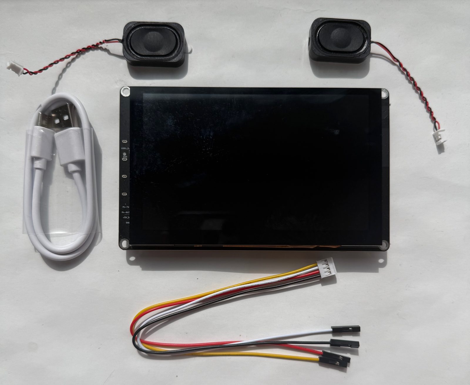
Specifications
ESP32-P4 · 131 × 80 mm · vs other ESP32 chips →Dimensions
About this board
Around the module: 32MB PSRAM, an IPS LCD 5.0" 800x480 display with touch, a microSD slot, a microphone (PDM MEMS), a speaker (2x 3W 4 Ohm), an amplifier (2x NS4168), battery charging (TP4059) via PH2.0-2P, status LEDs (Power, Charge) and Boot/Reset buttons.
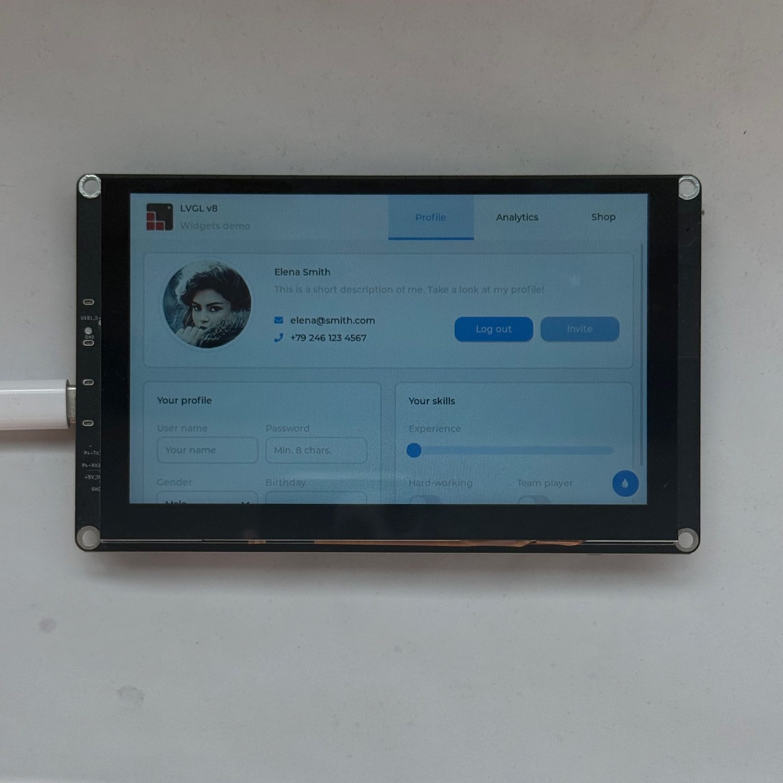
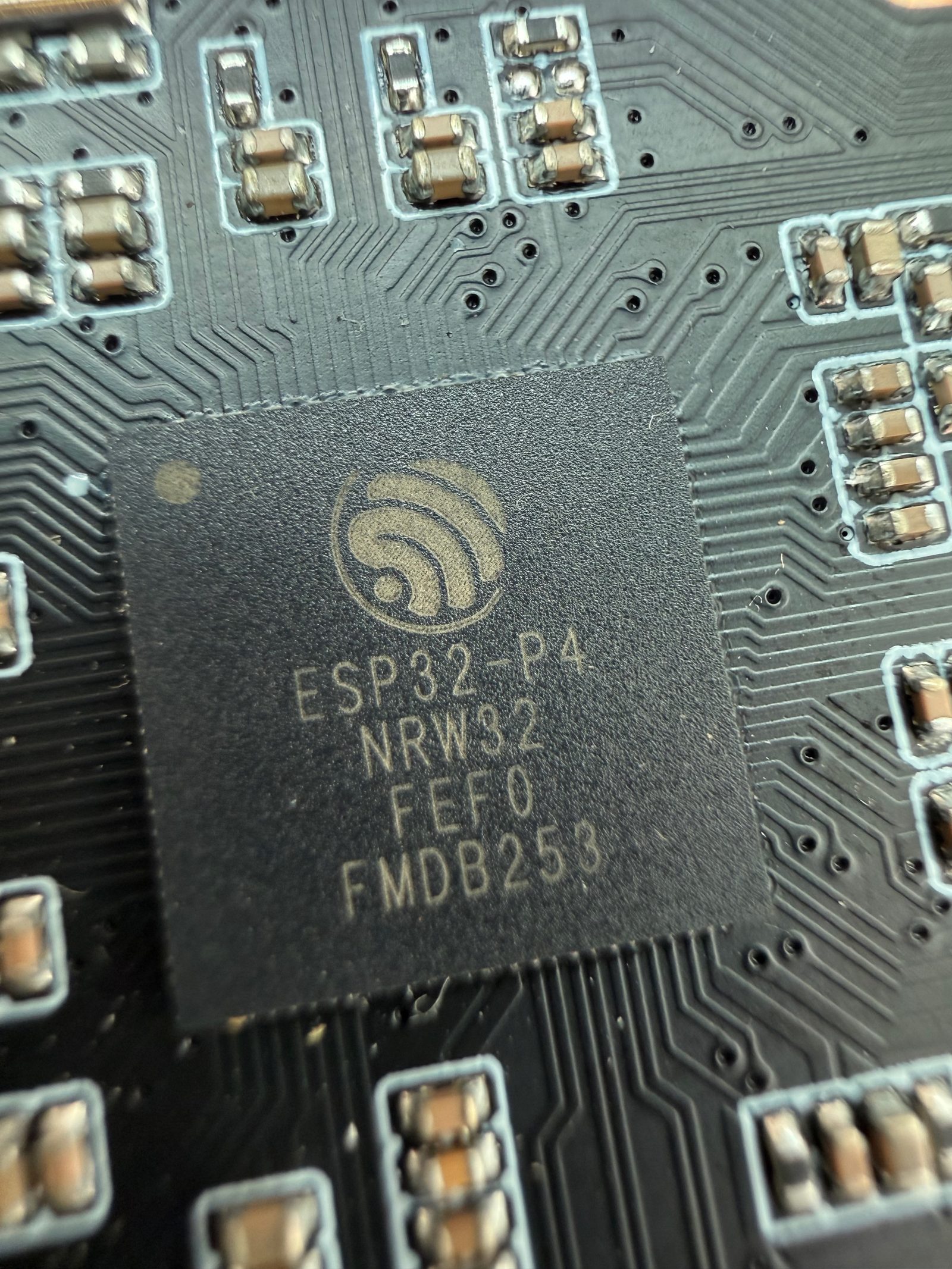
The Elecrow CrowPanel Advance 5.0 ESP32-P4 is the CrowPanel Advance formula with the controller swapped out. We've spent real time with this series - see our review of the ESP32-S3 CrowPanel Advance 7.0, and our three-generation CrowPanel comparison for how it stacks up against this board - and the format held up well: decent IPS panel, tidy Crowtail ports, and the clever swappable radio module socket. The consistent ceiling was the ESP32-S3 itself, which starts wheezing once an LVGL interface gets busy. This board answers that with an ESP32-P4: dual RISC-V cores at 400 MHz, 16 MB flash and 32 MB of PSRAM - four times what the S3 versions had to work with.
The P4 brings a wrinkle the S3 boards didn't have: no radio at all. Wi-Fi comes from an onboard ESP32-C6 over an SDIO link running ESP-Hosted firmware, which gets you 2.4 GHz Wi-Fi 6 and works transparently enough in ESP-IDF and ESPHome. Bluetooth 5.3 is on the spec sheet, but the hosted stack is Wi-Fi first - plan as if BLE isn't there. The module socket is the same one we plugged ESP32-H2 and nRF24 modules into on the 7.0, so Zigbee, Thread, LoRa or Wi-Fi HaLow remain a module away.
The "AI display" angle is more than marketing this time: two 3W speakers, a PDM microphone, and a MIPI-CSI camera header (2MP camera sold separately) that the P4's ISP and H.264 encoder can actually feed - voice-assistant panels and camera experiments are realistic here, not aspirational. A microSD slot, GPIO header and PH2.0 battery connector with charging round out the I/O.
Our honest read: this is first-wave P4 hardware. Current units ship engineering-sample silicon, ESP-IDF is the primary path, Arduino support leans on Elecrow's prepared package, and you'll copy their worked examples rather than wire things up from library docs. At around $43 it's one of the cheapest ways to get a P4 with a screen attached - but if you just need a dependable HMI today and 8 MB of PSRAM is enough, the S3-based CrowPanels are the more boring, safer buy.
- 5" 800x480 IPS panel (400 cd/m2) on a 16-bit RGB565 parallel bus, with GT911 5-point capacitive touch
- 2.4 GHz Wi-Fi 6 via onboard ESP32-C6-MINI-1 running ESP-Hosted over SDIO (Bluetooth 5.3 on paper, Wi-Fi-first in practice)
- Wireless module socket for optional ESP32-H2 (Zigbee/Thread), LoRa, nRF2401 or Wi-Fi HaLow modules, DIP-switch shared with UART1
- Dual 3W speakers on two NS4168 I2S amplifiers plus a PDM microphone for voice-assistant builds
- MIPI-CSI camera header - optional 2MP camera, backed by the P4's ISP for face detection and object tracking
- 32 MB PSRAM and 16 MB flash - LVGL at 800x480 fits comfortably
- Two USB-C ports - UART0 flashing/logs via CH340K, plus native USB 2.0 (also used for supplementary power)
- Crowtail I2C and UART ports, 2x8 GPIO header (IO26, IO29-IO32, IO47, IO48 + 3V3/5V rails), microSD (TF) slot
- PH2.0 battery connector with TP4059 charging (430mA max) and a power switch
- STC8 housekeeping MCU handles backlight brightness (I2C, address 0x2F) and touch reset
- Boot and Reset buttons; -20 to 70 degrees C operating range
FAQ
6 common questionsDoes the CrowPanel Advance 5.0 ESP32-P4 work with ESPHome?›
Does it have Bluetooth?›
How is this different from the ESP32-S3 CrowPanel Advance 5.0?›
How do I program it?›
Is a camera included?›
Can it do Zigbee or Thread?›
Where to buy
prices are typical street prices