
Espressif ESP32-P4-Function-EV-Board
Espressif ESP32-P4 evaluation board with 16MB flash, Ethernet, MIPI DSI/CSI, audio codec and an ESP32-C6-MINI-1 for Wi-Fi 6 and Bluetooth 5 LE.

Espressif ESP32-P4-Function-EV-Board Pinout
40 pins · 2.54 mm pitch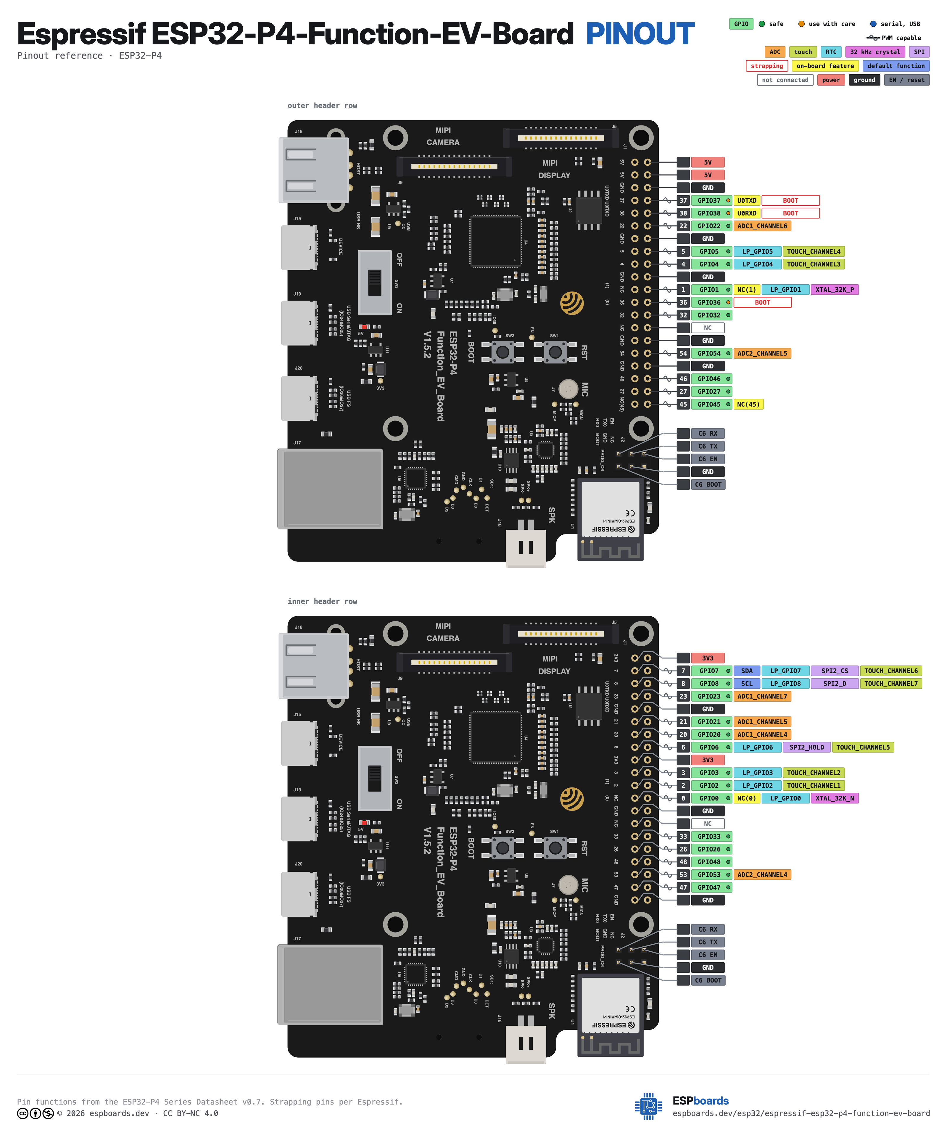
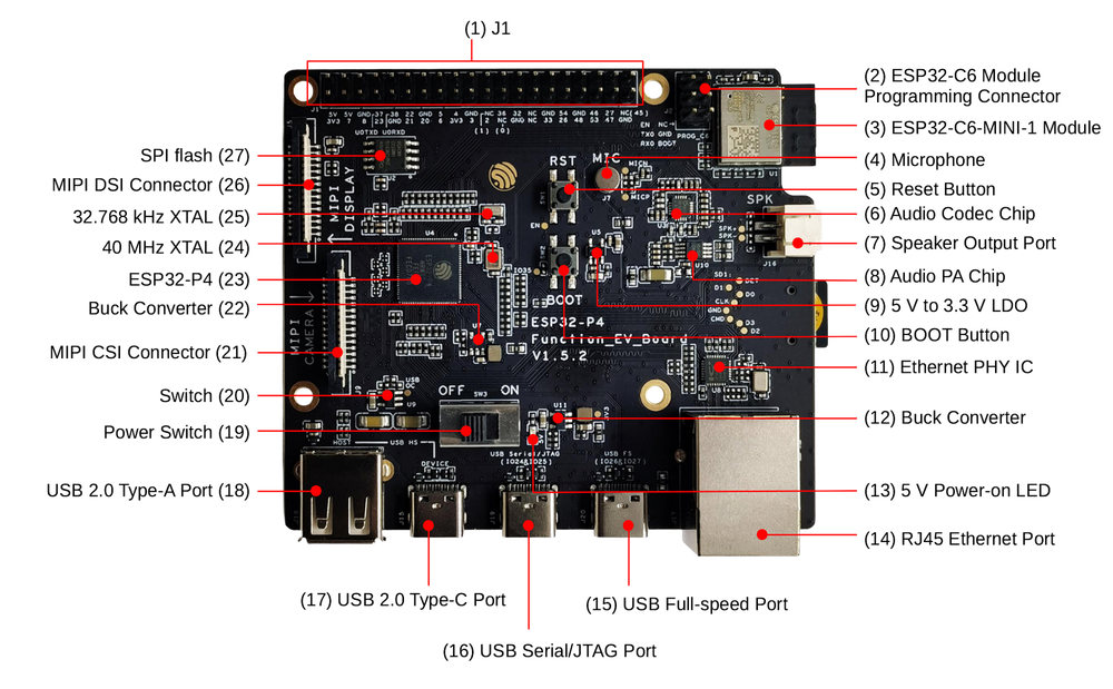
| Pin | GPIO | Labels | Status | Capabilities | Notes |
|---|---|---|---|---|---|
| 1 | - | 3V3 | power | - | Header J1 pin 1 - 3.3V supply |
| 2 | - | 5V | power | - | Header J1 pin 2 - 5V supply |
| 3 | 7 | 7GPIO7SDA | safe | pwm · i2c | Header J1 pin 3 - BSP I2C SDA (shared with onboard codec/touch) |
| 4 | - | 5V | power | - | Header J1 pin 4 - 5V supply |
| 5 | 8 | 8GPIO8SCL | safe | pwm · i2c | Header J1 pin 5 - BSP I2C SCL (shared with onboard codec/touch) |
| 6 | - | GND | ground | - | Header J1 pin 6 |
| 7 | 23 | 23GPIO23 | safe | adc · pwm | Header J1 pin 7 - ADC1 channel 7 |
| 8 | 37 | 37GPIO37U0TXD | strapping | uart · pwm | Header J1 pin 8 - UART0 TX |
| 9 | - | GND | ground | - | Header J1 pin 9 |
| 10 | 38 | 38GPIO38U0RXD | strapping | uart · pwm | Header J1 pin 10 - UART0 RX |
| 11 | 21 | 21GPIO21 | safe | adc · pwm | Header J1 pin 11 - ADC1 channel 5 |
| 12 | 22 | 22GPIO22 | safe | adc · pwm | Header J1 pin 12 - ADC1 channel 6 |
| 13 | 20 | 20GPIO20 | safe | adc · pwm | Header J1 pin 13 - ADC1 channel 4; also the chip's USB D+ pad in the BSP |
| 14 | - | GND | ground | - | Header J1 pin 14 |
| 15 | 6 | 6GPIO6 | safe | pwm | Header J1 pin 15 |
| 16 | 5 | 5GPIO5 | safe | pwm | Header J1 pin 16 |
| 17 | - | 3V3 | power | - | Header J1 pin 17 - 3.3V supply |
| 18 | 4 | 4GPIO4 | safe | pwm | Header J1 pin 18 |
| 19 | 3 | 3GPIO3 | safe | pwm | Header J1 pin 19 |
| 20 | - | GND | ground | - | Header J1 pin 20 |
| 21 | 2 | 2GPIO2 | safe | pwm | Header J1 pin 21 |
| 22 | 1 | NC(1)GPIO1 | safe | pwm | Header J1 pin 22 - not connected by default; disable XTAL_32K to route GPIO1 here |
| 23 | 0 | NC(0)GPIO0 | safe | pwm | Header J1 pin 23 - not connected by default; disable XTAL_32K to route GPIO0 here |
| 24 | 36 | 36GPIO36 | strapping | pwm | Header J1 pin 24 |
| 25 | - | GND | ground | - | Header J1 pin 25 |
| 26 | 32 | 32GPIO32 | safe | pwm | Header J1 pin 26 |
| 27 | - | NC | control | - | Header J1 pin 27 - no connection |
| 28 | - | NC | control | - | Header J1 pin 28 - no connection |
| 29 | 33 | 33GPIO33 | safe | pwm | Header J1 pin 29 |
| 30 | - | GND | ground | - | Header J1 pin 30 |
| 31 | 26 | 26GPIO26 | safe | pwm | Header J1 pin 31 - BSP LCD backlight for the 1024x600 panel |
| 32 | 54 | 54GPIO54 | safe | adc · pwm | Header J1 pin 32 - ADC2 channel 5 |
| 33 | 48 | 48GPIO48 | safe | pwm | Header J1 pin 33 |
| 34 | - | GND | ground | - | Header J1 pin 34 |
| 35 | 53 | 53GPIO53 | safe | adc · pwm | Header J1 pin 35 - ADC2 channel 4; BSP power amplifier enable |
| 36 | 46 | 46GPIO46 | safe | pwm | Header J1 pin 36 |
| 37 | 47 | 47GPIO47 | safe | pwm | Header J1 pin 37 |
| 38 | 27 | 27GPIO27 | safe | pwm | Header J1 pin 38 - BSP LCD reset for the 1024x600 panel |
| 39 | - | GND | ground | - | Header J1 pin 39 |
| 40 | 45 | NC(45)GPIO45 | safe | pwm | Header J1 pin 40 - not connected by default; disable SD_PWRn to route GPIO45 here |
Start with these
23 pins with no boot or system involvementFreely assignable - no strapping, flash, USB or JTAG duties. Ideal first picks for buttons, sensors and LEDs.
Fine - with a little care
3 pins · 2 things to know37GPIO3738GPIO38 Strapping pin; participates in chip boot-mode control (see ESP32-P4 TRM, Chip Boot Control). Strapping
Sampled at reset as a boot-mode strap; avoid holding it at a fixed level during boot unless intentionally configuring boot mode. Free after reset.
- 37Strapping pin; participates in chip boot-mode control (see ESP32-P4 TRM, Chip Boot Control).
- 38Strapping pin; participates in chip boot-mode control (see ESP32-P4 TRM, Chip Boot Control).
36GPIO36 Strapping pin; part of boot-mode selection (with GPIO35) and controls ROM-message printing to UART0. Strapping
Sampled at reset for boot mode and log output; driving it at boot can change the boot mode or silence/enable ROM logs. Free after reset.
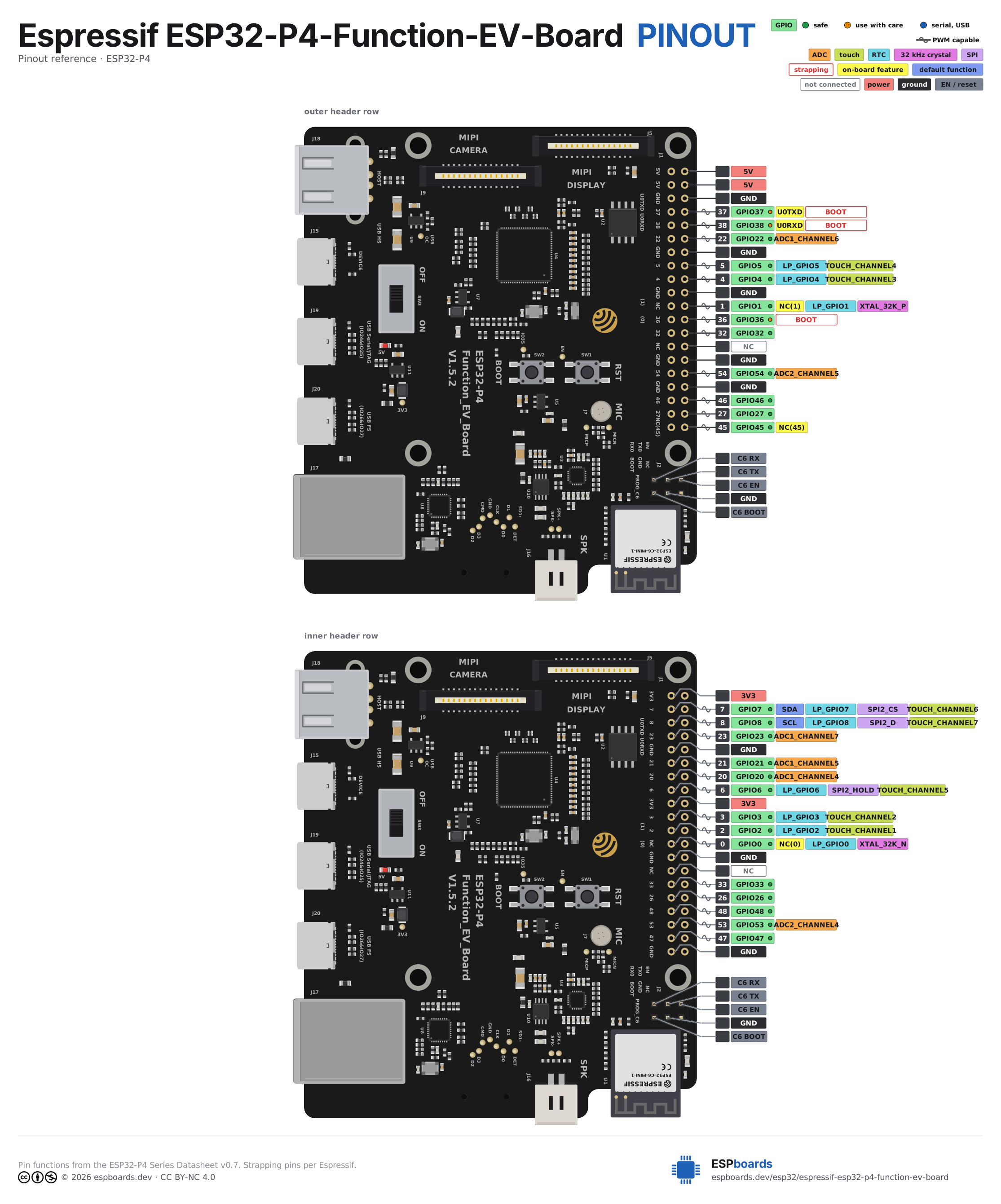
The Espressif ESP32-P4-Function-EV-Board pinout brings out 40 pins at a 2.54 mm pitch - 26 usable GPIO alongside the 3V3, 5V and GND power rails.
Peripheral wiring is straightforward: I²C is mapped to SDA on GPIO7 and SCL on GPIO8.
Beyond plain digital I/O you get 6 ADC-capable pins for sensors and battery monitoring and PWM on every GPIO.
3 of the exposed pins carry boot-time or system duties on the ESP32-P4 (37, 38 and 36) - check the guidance above before wiring anything to them. 7, 8, 23, 21 and 19 more are free of any such role - the safest first picks.
Getting started
flash your first firmware in ~2 minutesBoard: ESP32P4 Dev Module USB CDC On Boot: Enabled Flash Size: 16MB (128Mb) PSRAM: QSPI PSRAM Partition Scheme: 16M Flash (3MB APP/9.9MB FATFS) Upload Speed: 921600
// toggle GPIO7 - wire an LED and resistor to it
void setup() {
  pinMode(7, OUTPUT);
}
void loop() {
  digitalWrite(7, HIGH); delay(500);
  digitalWrite(7, LOW);  delay(500);
}[env:espressif-esp32-p4-function-ev-board]
platform = https://github.com/pioarduino/platform-espressif32/releases/download/stable/platform-espressif32.zip
board = esp32dev
framework = arduino
monitor_speed = 115200
upload_speed = 921600
board_build.arduino.memory_type = qio_qspi
build_flags = -DBOARD_HAS_PSRAMesp32dev - or type it after board =.esp32:
board: esp32dev
variant: esp32p4
framework:
type: esp-idf
psram:
mode: quad
speed: 80MHz
# blink - GPIO7
output:
- platform: gpio
pin: 7
id: led_out
light:
- platform: binary
name: "LED"
output: led_outesp32dev (same ids as PlatformIO).esptool.py --chip esp32p4 --port /dev/ttyACM0 \
--baud 921600 write_flash 0x2000 firmware.bin--port = your /dev/tty* (macOS/Linux) or COMx (Windows).Good to know
board-specific quirks worth 60 secondsEspressif lists this board as obsolete and points to the ESP32-P4X-Function-EV-Board (chip revision v3.1) as its replacement - same PCB and pinout, new silicon. Boards already out there also come in two revisions: v1.5.2 replaced the v1.4's CP2102N USB-to-UART debug port with the ESP32-P4's built-in USB Serial/JTAG, added a Full-speed USB OTG Type-C port and removed IO24/IO25 from the header. Check which…
Espressif lists this board as obsolete and points to the ESP32-P4X-Function-EV-Board (chip revision v3.1) as its replacement - same PCB and pinout, new silicon. Boards already out there also come in two revisions: v1.5.2 replaced the v1.4's CP2102N USB-to-UART debug port with the ESP32-P4's built-in USB Serial/JTAG, added a Full-speed USB OTG Type-C port and removed IO24/IO25 from the header.
Check which revision you have before following a guide - the port layout and header pins differ between v1.4 and v1.5.2.
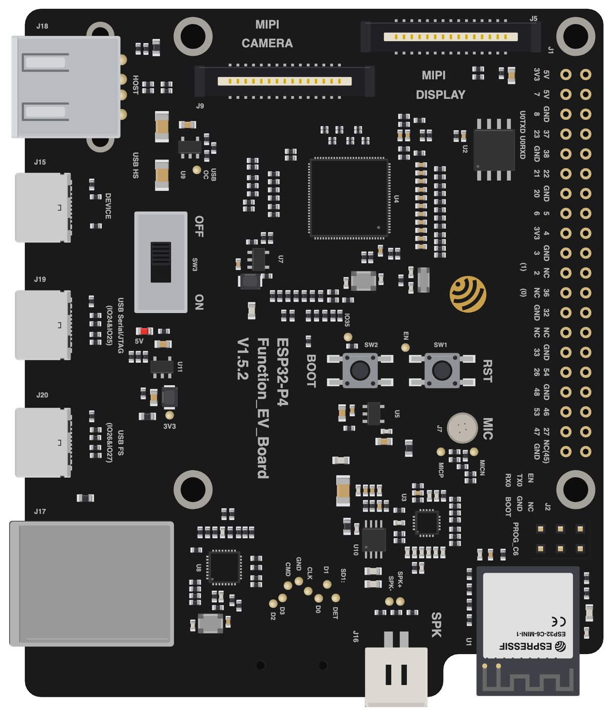
The camera connects with a forward ribbon cable (contacts on the same side at both ends), while the LCD uses a reverse cable (contacts on opposite sides). Swapping them or fitting the wrong type leaves the display or camera dead.
Downloads
Free for non-commercial use, credit espboards.dev · License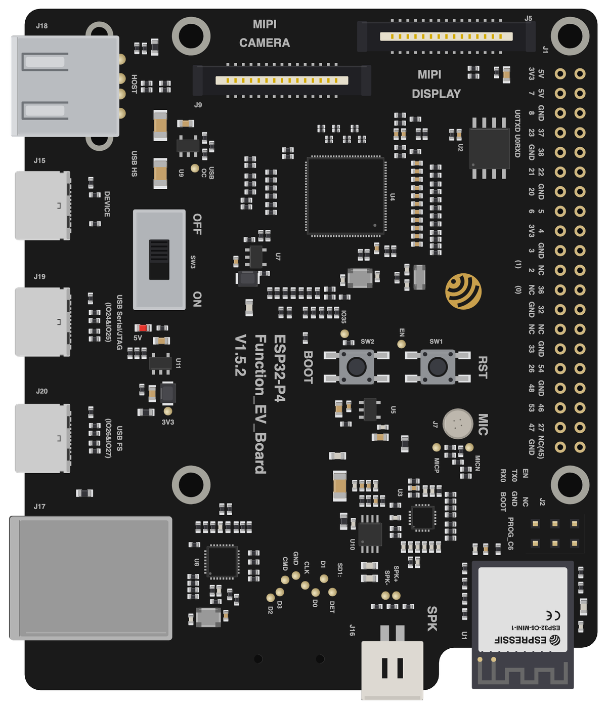
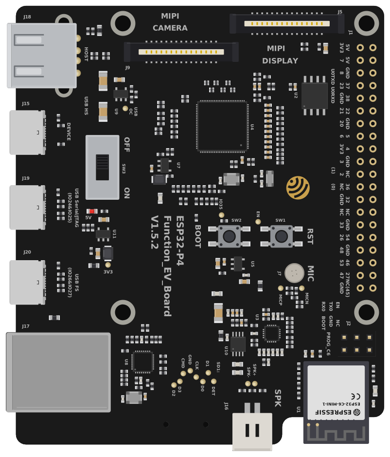
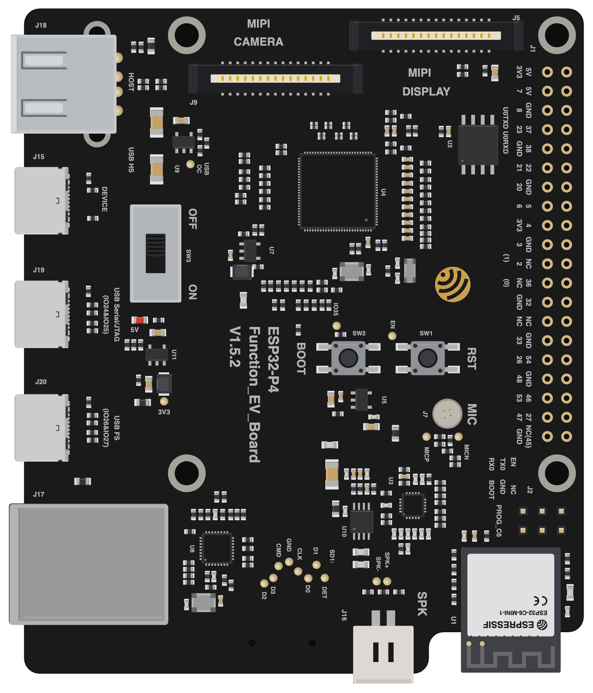
Board illustration
The bare Espressif ESP32-P4-Function-EV-Board board drawn to scale at 88 × 74 mm, with no pin labels on it. Made for slide decks, wiring diagrams and project write-ups where a photo is too busy. Take the scalable SVG for print or editing, the high-resolution PNG to drop straight in, or the transparent PNG when you need it with no background behind it.
Pinout diagram
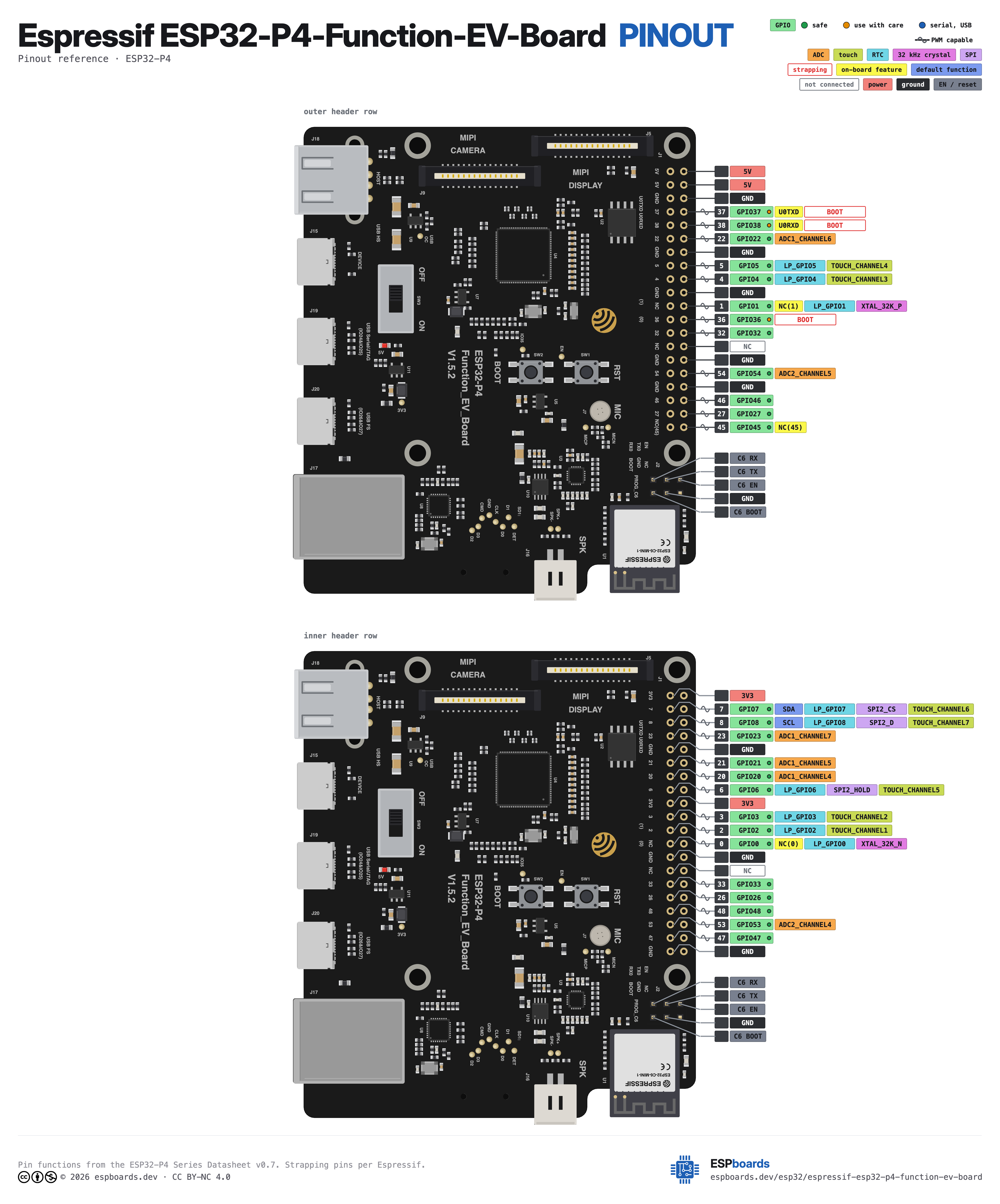
Every pin on both sides of the board with its functions, drawn by ESPboards from the ESP32-P4 Series Datasheet v0.7 - the same sheet shown at the top of this page. The PNG is a high-resolution image for screens, the SVG is vector so it stays sharp at any size, and the PDF is laid out to print on A4 or Letter.
Yours to use, share and adapt for non-commercial work, as long as you credit espboards.dev - the full terms and ready-made credit lines are here.
Specifications
ESP32-P4 · 88 × 74 mm · vs other ESP32 chips →Dimensions

About this board
At 88 × 74 mm it's the smallest ESP32-P4 board we've measured.
The $55.44 price tag is typical for an ESP32-P4 board.
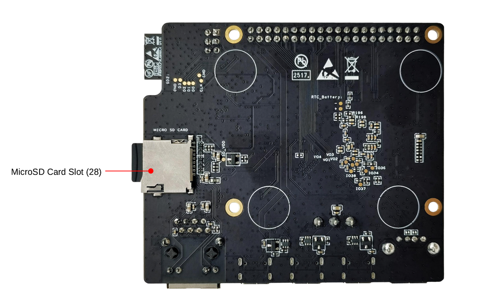
Around the module: 32MB PSRAM, an LCD 7" 1024x600 display with touch, a camera (2MP (MIPI CSI)), a microSD slot, a microphone, an audio codec (ES8311), an amplifier (NS4150B), wired Ethernet (IP101GR), status LEDs (5V Power) and Reset/Boot buttons.
It flashes over native USB - no serial-converter driver needed, which isn't a given among ESP32-P4 boards.
- ESP32-C6-MINI-1 co-processor module for 2.4 GHz Wi-Fi 6 and Bluetooth 5 LE
- USB 2.0 OTG High-Speed on a Type-C (device) and a Type-A (host, up to 500 mA) port - the two cannot be used at the same time
- Kit ships with a 7-inch 1024x600 capacitive touch screen and a 2MP MIPI CSI camera module
- Onboard power switch
- Early V0.1 engineering-sample chips had no working USB Serial/JTAG and no ADC calibration
Where to buy
prices are typical street pricesResources
Similar boards


