
M5Stack Tab5
Tablet-style ESP32-P4 terminal - 5" 720p touch display, 2MP camera, RS-485 and a swappable camcorder battery. Wi-Fi 6 comes from an onboard ESP32-C6.

M5Stack Tab5 Pinout
53 pins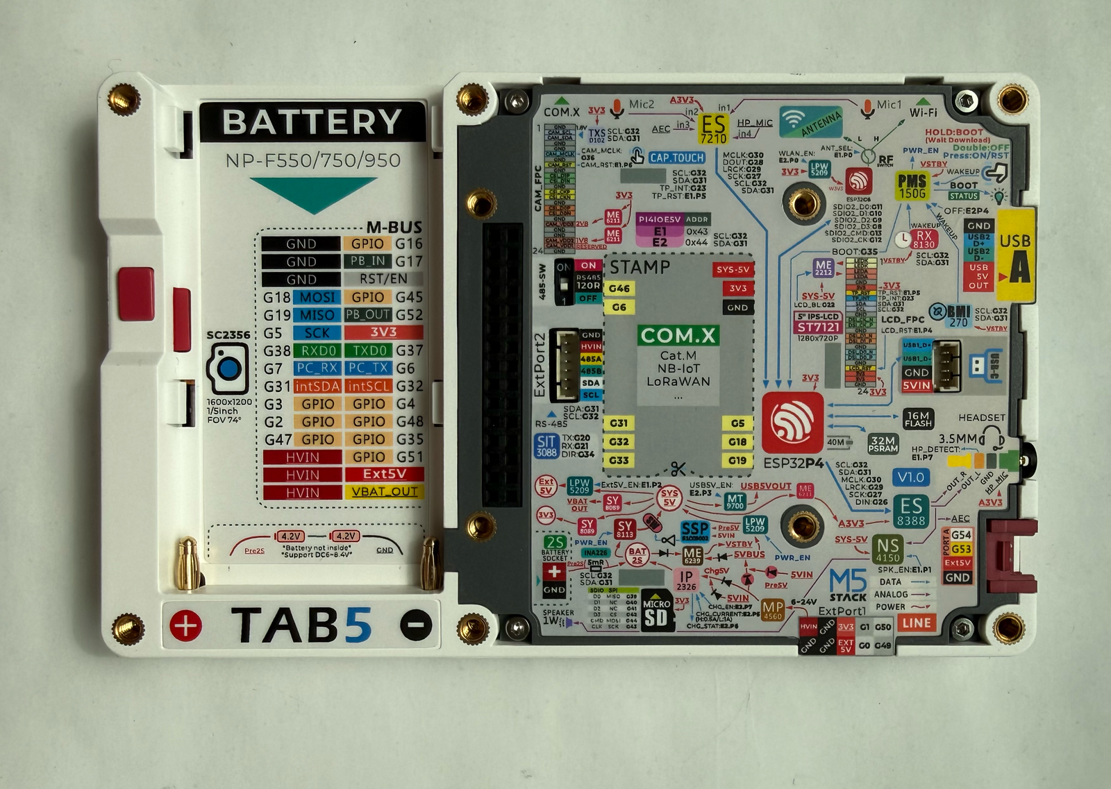
| Pin | GPIO | Labels | Status | Capabilities | Notes |
|---|---|---|---|---|---|
| 1 | 0 | G0EXT_PORT1 | safe | - | |
| 2 | 1 | G1EXT_PORT1 | safe | - | |
| 3 | 2 | G2M5_BUS | safe | - | |
| 4 | 3 | G3M5_BUS | safe | - | |
| 5 | 4 | G4M5_BUS | safe | - | |
| 6 | 5 | G5SCK | safe | spi | |
| 7 | 6 | G6PC_TX | uart | uart | |
| 8 | 7 | G7PC_RX | uart | uart | |
| 9 | 8 | G8C6_SDIO2_D3 | safe | - | Reserved - SDIO2 data to the ESP32-C6 radio (ESP-Hosted link), not usable as GPIO |
| 10 | 9 | G9C6_SDIO2_D2 | safe | - | Reserved - SDIO2 data to the ESP32-C6 radio, not usable as GPIO |
| 11 | 10 | G10C6_SDIO2_D1 | safe | - | Reserved - SDIO2 data to the ESP32-C6 radio, not usable as GPIO |
| 12 | 11 | G11C6_SDIO2_D0 | safe | - | Reserved - SDIO2 data to the ESP32-C6 radio, not usable as GPIO |
| 13 | 12 | G12C6_SDIO2_CK | safe | - | Reserved - SDIO2 clock to the ESP32-C6 radio, not usable as GPIO |
| 14 | 13 | G13C6_SDIO2_CMD | safe | - | Reserved - SDIO2 command to the ESP32-C6 radio, not usable as GPIO |
| 15 | 14 | G14C6_IO2 | safe | - | Reserved - wired to ESP32-C6 IO2, part of the radio link |
| 16 | 15 | G15C6_RESET | safe | - | Reserved - ESP32-C6 reset line, driven by the P4 |
| 17 | 16 | G16M5_BUS | safe | - | |
| 18 | 17 | G17M5_BUS | safe | - | |
| 19 | 18 | G18MOSI | safe | spi | |
| 20 | 19 | G19MISO | safe | spi | |
| 21 | 20 | G20RS485_TX | uart | uart | Wired to the SIT3088 RS-485 transceiver (driver input) |
| 22 | 21 | G21RS485_RX | uart | uart | Wired to the SIT3088 RS-485 transceiver (receiver output) |
| 23 | 22 | G22LCD_BL | safe | - | Internal - LCD backlight enable |
| 24 | 23 | G23TP_INT | safe | - | Internal - touch controller interrupt |
| 25 | 26 | G26I2S_DSDIN | safe | - | Internal I2S data out to the ES8388 codec (speaker/headphones) |
| 26 | 27 | G27I2S_SCLK | safe | - | Internal I2S bit clock (ES8388 + ES7210) |
| 27 | 28 | G28I2S_ASDOUT | safe | - | Internal I2S data in from the ES7210 mic front-end |
| 28 | 29 | G29I2S_LRCK | safe | - | Internal I2S word clock (ES8388 + ES7210) |
| 29 | 30 | G30I2S_MCLK | safe | - | Internal I2S master clock (ES8388 + ES7210) |
| 30 | 31 | G31SDA | safe | i2c | Internal I2C SDA (touch, IMU, RTC, INA226, IO expanders) - shared out on M5-Bus and STAMP; add devices, don't repurpose |
| 31 | 32 | G32SCL | safe | i2c | Internal I2C SCL - same shared bus as G31 |
| 32 | 33 | G33STAMP | safe | - | |
| 33 | 34 | G34RS485_DIR | strapping | - | RS-485 driver-enable for the SIT3088 |
| 34 | 35 | G35M5_BUSBOOT | strapping | - | BOOT signal (also M5-Bus pin 24) - hold at boot for download mode |
| 35 | 36 | G36CAM_MCLK | strapping | - | Internal - camera master clock (MIPI-CSI) |
| 36 | 37 | G37TXD0 | strapping | uart | |
| 37 | 38 | G38RXD0 | strapping | uart | |
| 38 | 39 | G39SD_DAT0SD_MISO | safe | spi | microSD slot - DAT0 in SDIO mode, MISO in SPI mode |
| 39 | 40 | G40SD_DAT1 | safe | - | microSD slot - DAT1 (SDIO mode only) |
| 40 | 41 | G41SD_DAT2 | safe | - | microSD slot - DAT2 (SDIO mode only) |
| 41 | 42 | G42SD_DAT3SD_CS | safe | spi | microSD slot - DAT3 / chip select |
| 42 | 43 | G43SD_CLKSD_SCK | safe | spi | microSD slot - clock |
| 43 | 44 | G44SD_CMDSD_MOSI | safe | spi | microSD slot - command / MOSI |
| 44 | 45 | G45M5_BUS | safe | - | |
| 45 | 46 | G46STAMP | safe | - | |
| 46 | 47 | G47M5_BUS | safe | - | |
| 47 | 48 | G48M5_BUS | safe | - | |
| 48 | 49 | G49EXT_PORT1 | safe | - | |
| 49 | 50 | G50EXT_PORT1 | safe | - | |
| 50 | 51 | G51M5_BUS | safe | - | |
| 51 | 52 | G52PB_OUT | safe | - | |
| 52 | 53 | G53PORT_A | safe | - | |
| 53 | 54 | G54PORT_A | safe | - |
Start with these
48 pins with no boot or system involvementFreely assignable - no strapping, flash, USB or JTAG duties. Ideal first picks for buttons, sensors and LEDs.
Fine - with a little care
5 pins · 4 things to knowG34GPIO34 Strapping pin; selects the JTAG signal source (external JTAG pins vs. the USB Serial/JTAG controller). Floating by default. Strapping
Sampled at reset to choose the JTAG source; driving it at boot can redirect or disable JTAG debugging. Free to use as a regular GPIO after reset.
G35GPIO35 Strapping pin; primary chip boot-mode select. HIGH (default, internal weak pull-up) = SPI boot; LOW = Joint Download (flashing) boot. Strapping
Must stay HIGH at reset for normal boot; pulling it LOW forces download/programming mode. Freed for GPIO use after reset.
G36GPIO36 Strapping pin; part of boot-mode selection (with GPIO35) and controls ROM-message printing to UART0. Strapping
Sampled at reset for boot mode and log output; driving it at boot can change the boot mode or silence/enable ROM logs. Free after reset.
G37GPIO37G38GPIO38 Strapping pin; participates in chip boot-mode control (see ESP32-P4 TRM, Chip Boot Control). Strapping
Sampled at reset as a boot-mode strap; avoid holding it at a fixed level during boot unless intentionally configuring boot mode. Free after reset.
- G37Strapping pin; participates in chip boot-mode control (see ESP32-P4 TRM, Chip Boot Control).
- G38Strapping pin; participates in chip boot-mode control (see ESP32-P4 TRM, Chip Boot Control).
All 53 pins on the M5Stack Tab5 are usable GPIO.
Peripheral wiring is straightforward: I²C is mapped to SDA on GPIO31 and SCL on GPIO32, while the SPI bus (MOSI, MISO, SCK) is broken out in full.
5 of the exposed pins carry boot-time or system duties on the ESP32-P4 (G34, G35, G36 and 2 more) - check the guidance above before wiring anything to them. G0, G1, G2, G3 and 44 more are free of any such role - the safest first picks.
Pinout notes The M5Stack Tab5 exposes its GPIO through the 30-pin M5-Bus connector (GPIO, SPI on G5/G18/G19, UART0 on G37/G38, the internal I2C bus, and 6-24V HVIN/5V/3V3…
The M5Stack Tab5 exposes its GPIO through the 30-pin M5-Bus connector (GPIO, SPI on G5/G18/G19, UART0 on G37/G38, the internal I2C bus, and 6-24V HVIN/5V/3V3 rails), a screw-terminal ExtPort1 breaking out G0/G1/G49/G50 alongside HVIN/5V/3V3, and one Grove (HY2.0-4P) port on G53/G54. Reserved STAMP pads (with G6, G33, G46 and the SPI/I2C buses) accept Cat-M, NB-IoT or LoRaWAN modules.
Everything internal shares one I2C bus (G31 SDA / G32 SCL): touch controller, BMI270 IMU, RX8130CE RTC, INA226 power monitor, camera control and two PI4IOE5V6408 IO expanders (0x43/0x44) that gate most power rails and resets. The microSD slot sits on G39-G44 (SPI or SDIO mode), and the ESP32-C6 radio occupies G8-G15 as a dedicated SDIO link - those pins are not available for your own use.
The RS-485 transceiver uses G20 (TX), G21 (RX) and G34 (driver enable). Like other M5Stack cores, display reset, touch reset and several power switches live behind the IO expanders rather than direct GPIOs - drivers must initialize those first.
Getting started
flash your first firmware in ~2 minutesBoard: ESP32P4 Dev Module USB CDC On Boot: Enabled Flash Size: 16MB (128Mb) PSRAM: QSPI PSRAM Partition Scheme: 16M Flash (3MB APP/9.9MB FATFS) Upload Speed: 921600
// toggle GPIO0 - wire an LED and resistor to it
void setup() {
  pinMode(0, OUTPUT);
}
void loop() {
  digitalWrite(0, HIGH); delay(500);
  digitalWrite(0, LOW);  delay(500);
}[env:m5stack-tab5]
platform = https://github.com/pioarduino/platform-espressif32/releases/download/stable/platform-espressif32.zip
board = esp32dev
framework = arduino
monitor_speed = 115200
upload_speed = 921600
board_build.arduino.memory_type = qio_qspi
build_flags = -DBOARD_HAS_PSRAMesp32dev - or type it after board =.esp32:
board: esp32dev
variant: esp32p4
framework:
type: esp-idf
psram:
mode: quad
speed: 80MHz
# blink - GPIO0
output:
- platform: gpio
pin: 0
id: led_out
light:
- platform: binary
name: "LED"
output: led_outesp32dev (same ids as PlatformIO).esptool.py --chip esp32p4 --port /dev/ttyACM0 \
--baud 921600 write_flash 0x2000 firmware.bin--port = your /dev/tty* (macOS/Linux) or COMx (Windows).Good to know
board-specific quirks worth 60 seconds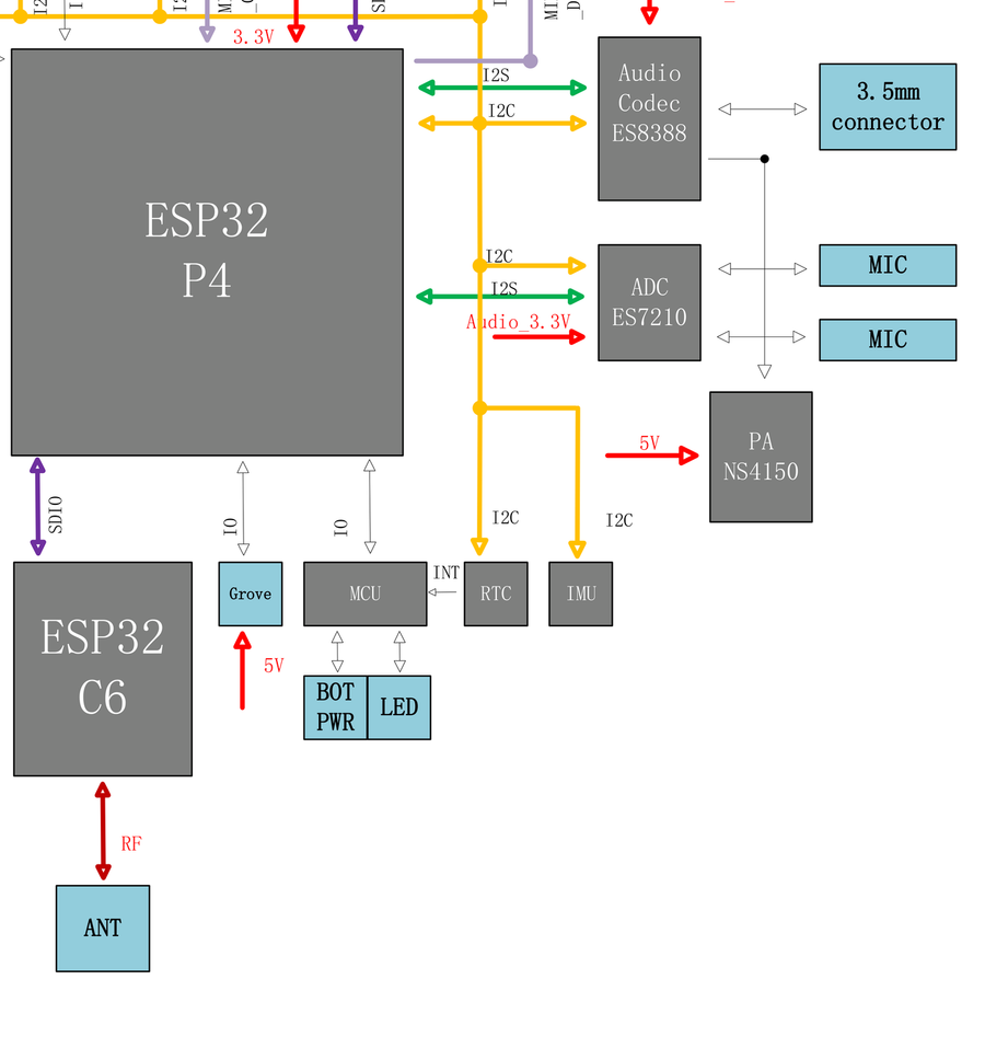
Wireless comes from an ESP32-C6-MINI-1U wired to the P4 over a dedicated SDIO link (G8-G15) running ESP-Hosted firmware. In ESP-IDF, Arduino and ESPHome this is largely transparent - you configure Wi-Fi as usual - but features are gated by the hosted stack, not the C6's silicon: Bluetooth, Thread and Zigbee are effectively unavailable even though the module supports them. If Wi-Fi breaks after a framework…
Wireless comes from an ESP32-C6-MINI-1U wired to the P4 over a dedicated SDIO link (G8-G15) running ESP-Hosted firmware. In ESP-IDF, Arduino and ESPHome this is largely transparent - you configure Wi-Fi as usual - but features are gated by the hosted stack, not the C6's silicon: Bluetooth, Thread and Zigbee are effectively unavailable even though the module supports them.
If Wi-Fi breaks after a framework update, check that the C6's ESP-Hosted firmware version matches what your P4-side stack expects - the two are updated separately.
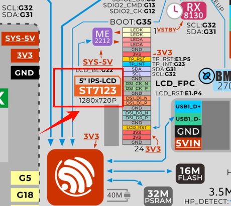
Early Tab5 units pair an ILI9881C display driver with a GT911 touch controller; newer revisions moved to ST7123/ST7121 chips that integrate display and touch. M5Stack's own firmware handles both, but third-party support lags - ESPHome currently supports only the ILI9881C/GT911 combination, and there's no external marking to tell revisions apart before flashing. If a known-good ESPHome or LVGL config gives…
Early Tab5 units pair an ILI9881C display driver with a GT911 touch controller; newer revisions moved to ST7123/ST7121 chips that integrate display and touch. M5Stack's own firmware handles both, but third-party support lags - ESPHome currently supports only the ILI9881C/GT911 combination, and there's no external marking to tell revisions apart before flashing.
If a known-good ESPHome or LVGL config gives you a black screen or dead touch on a brand-new unit, suspect the display revision before debugging your YAML.
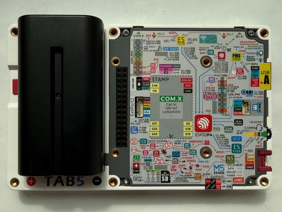
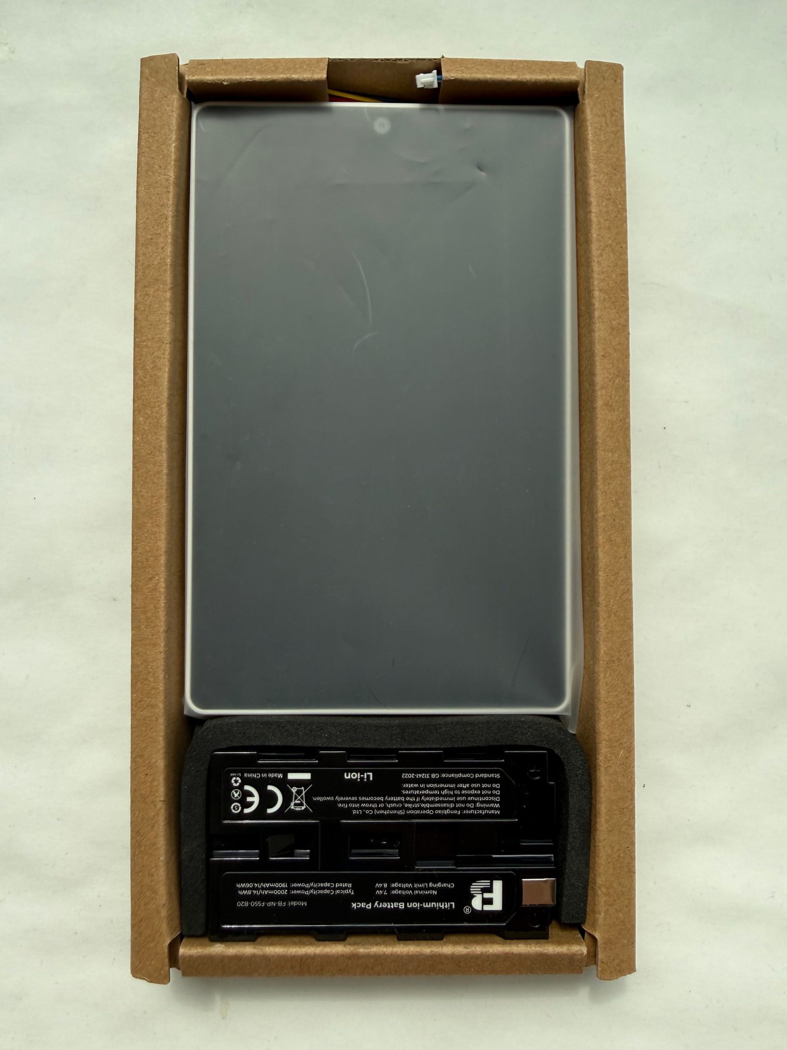
The Tab5 takes a removable two-cell NP-F550 pack (7.4V / 2000mAh) - a decades-old camcorder standard, so high-capacity third-party packs are everywhere and swaps take seconds. An IP2326 handles 2-cell charging over USB-C and an INA226 (I2C 0x41) measures real voltage and current, so firmware can report an honest battery percentage. For permanent installs, skip the battery entirely - the RS-485 terminal accepts…
The Tab5 takes a removable two-cell NP-F550 pack (7.4V / 2000mAh) - a decades-old camcorder standard, so high-capacity third-party packs are everywhere and swaps take seconds. An IP2326 handles 2-cell charging over USB-C and an INA226 (I2C 0x41) measures real voltage and current, so firmware can report an honest battery percentage.
For permanent installs, skip the battery entirely - the RS-485 terminal accepts 6-24V DC, which suits wall-panel and DIN-cabinet wiring better than USB.
Gallery
6 photos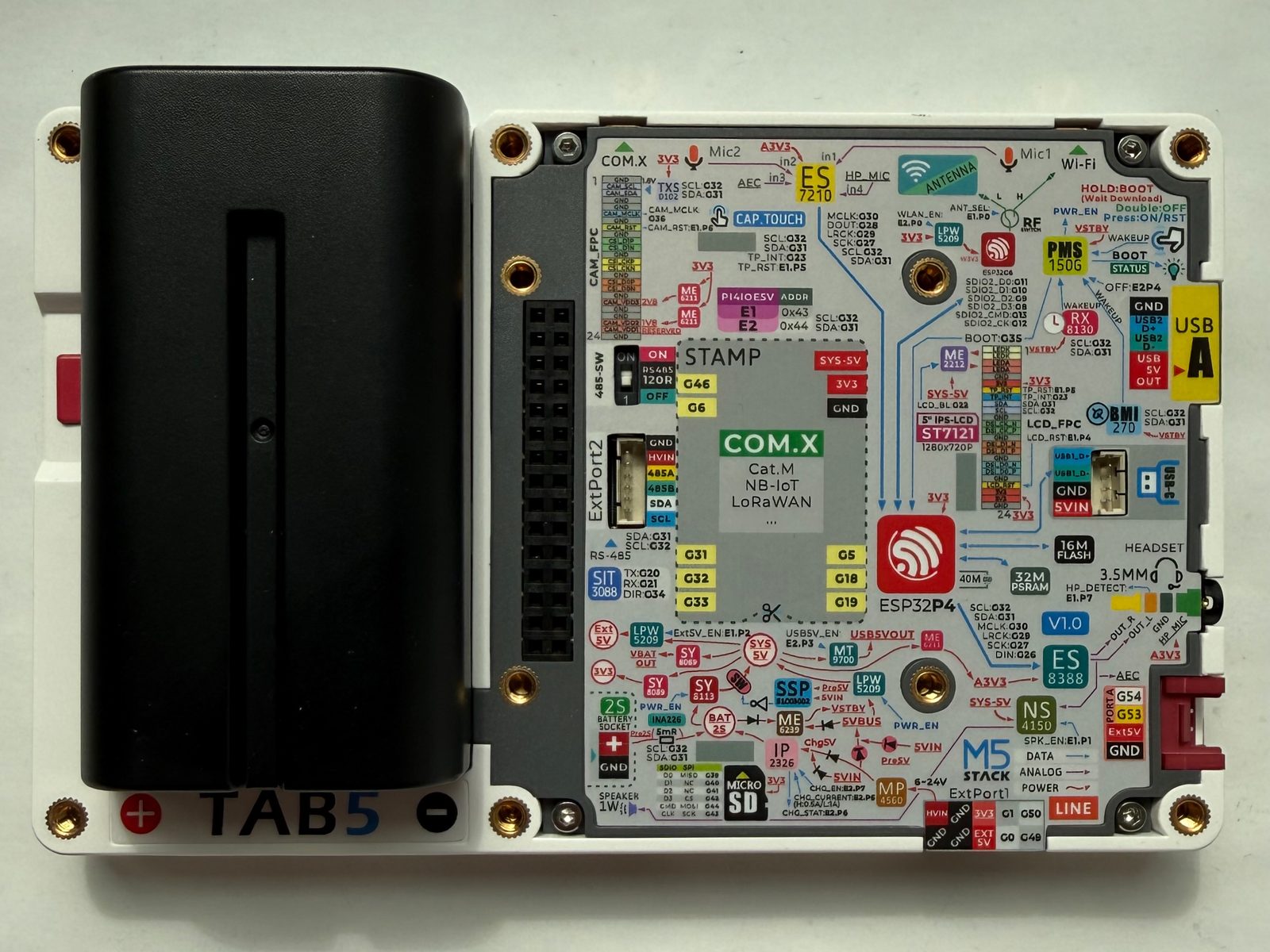
Specifications
ESP32-P4 · 128 × 80 mm · vs other ESP32 chips →Dimensions
About this board
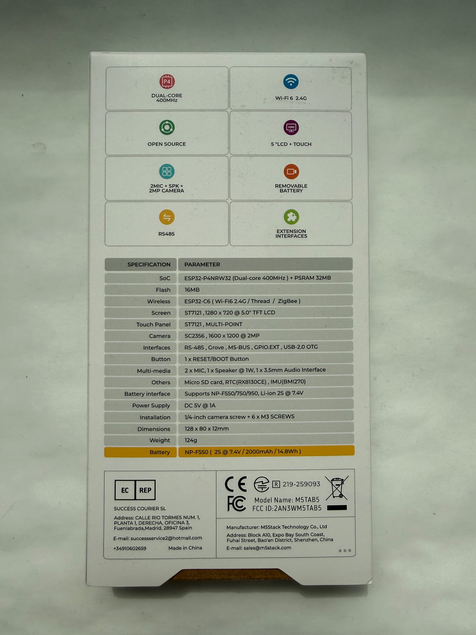
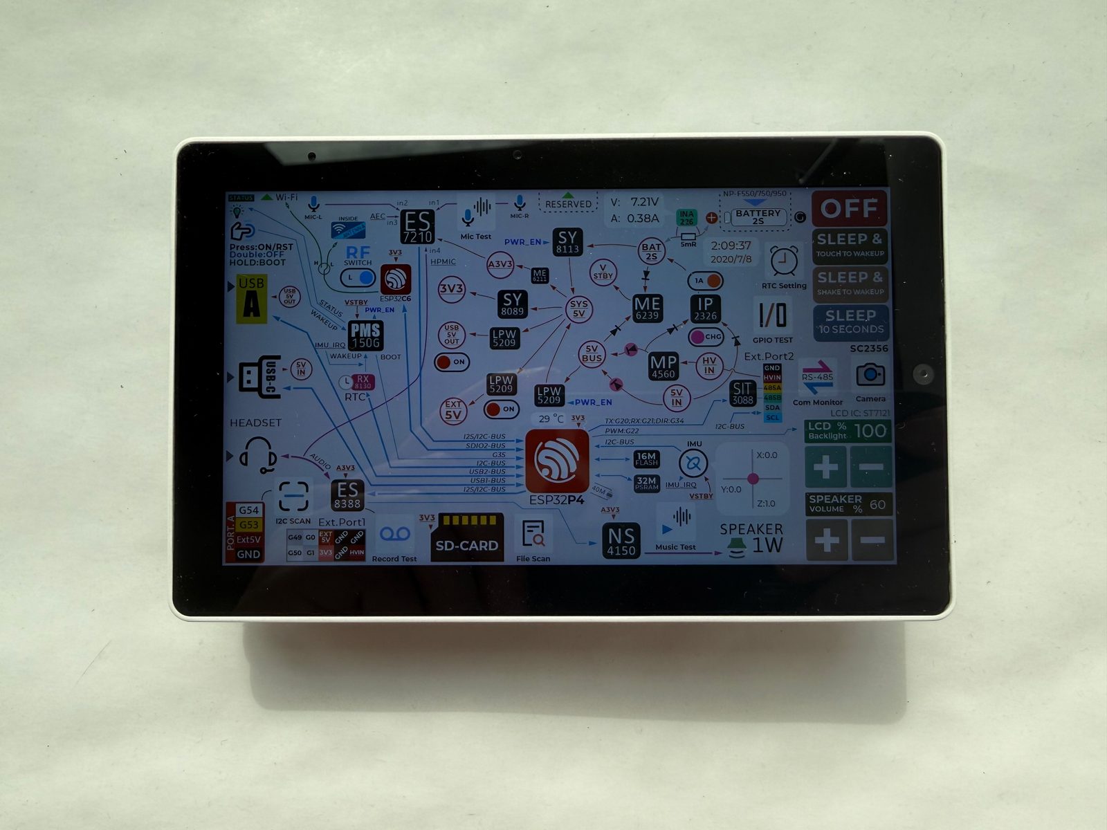
Around the module: 32MB PSRAM, an IPS LCD 5.0" 1280x720 display with touch, an SC2356 camera (2MP), a microSD slot, a microphone (Dual mic array), a speaker, an audio codec (ES8388 + ES7210 AEC), an amplifier (NS4150B), a BMI270 IMU, an RX8130CE RTC, a battery fuel gauge (INA226), an RS485 interface (SIT3088) and battery charging (IP2326) via NP-F550 bay.
It flashes over native USB - no serial-converter driver needed.
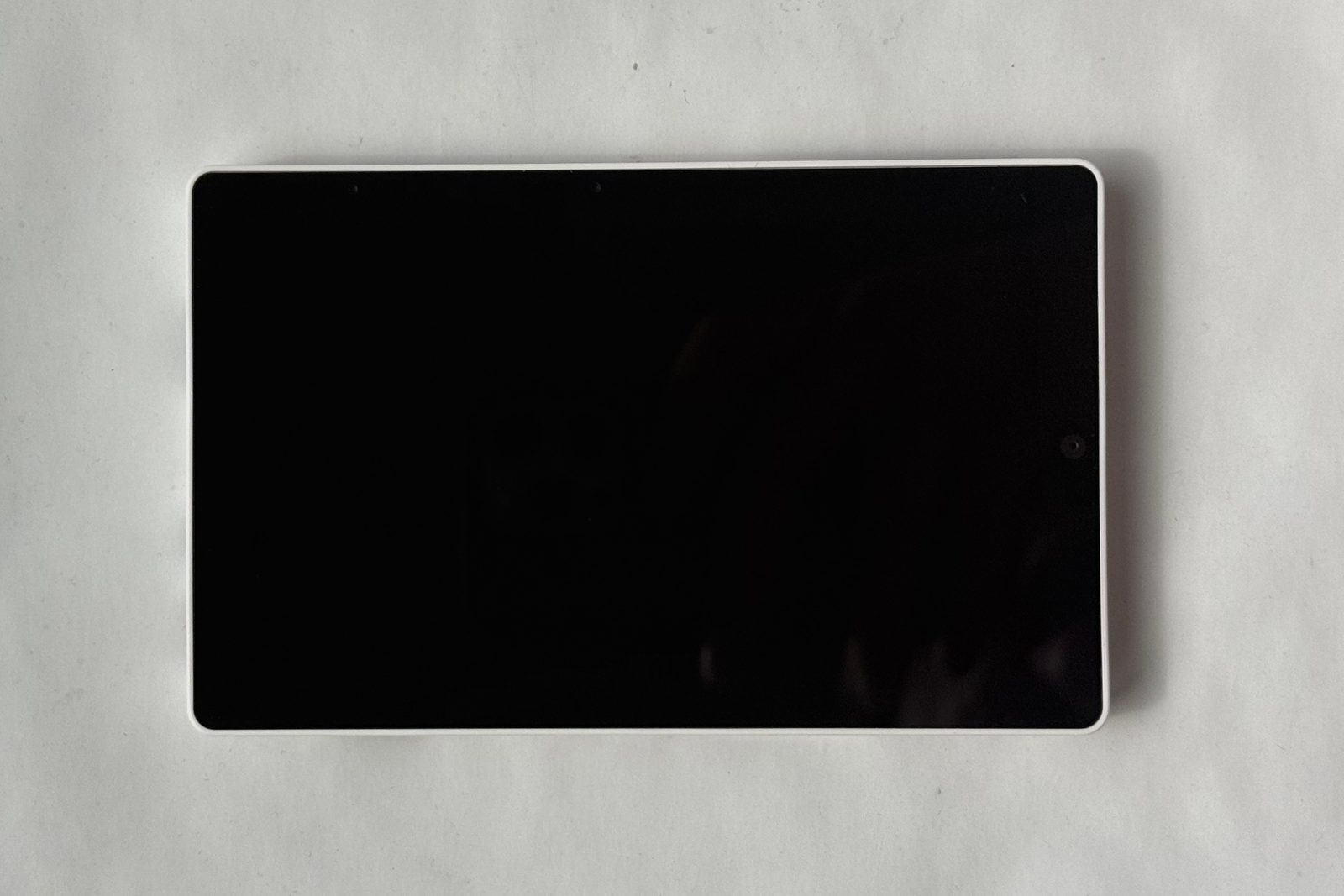
Honest admission: the M5Stack Tab5 is the first ESP32 device I've handled where I keep forgetting there's an ESP32 inside. You pick it up and it's just... a small tablet. Glass front, 5" 720p touchscreen, a power button, a camcorder battery clipped on the back. Then you flash it over USB-C like any other dev board and remember there's no Linux under there - the whole thing runs bare on a microcontroller.
That microcontroller is the ESP32-P4 - dual-core RISC-V at 360 MHz, 16 MB flash, 32 MB PSRAM in the package - driving the display over MIPI-DSI. One thing to internalize before buying: the P4 has no radio at all. Wi-Fi 6 comes from an onboard ESP32-C6 module wired over SDIO, running Espressif's ESP-Hosted firmware. Day to day you don't notice, but wireless features arrive at the pace of that hosted stack, not the C6's spec sheet - which is why there's no practical Bluetooth here.
The rest of the hardware list is long the way M5Stack likes it: 2MP camera, dual mics with echo cancellation, a speaker and a headphone jack, IMU, RTC, microSD, USB-A host, and - the tell that this is aimed at industrial panels, not hobby desks - an RS-485 port that doubles as a 6-24V power input. The removable NP-F550 pack is a genuinely good call: it's a decades-old camcorder standard, spares are cheap everywhere, and swapping takes two seconds. M5Stack claims about 6 hours per charge, and with a 14.8 Wh pack driving a 5" backlight, that math checks out.
The honest caveat is software maturity. This is a first-wave ESP32-P4 product: ESP-IDF is the serious path, Arduino support for the P4 is younger than for the S3, and ESPHome - which otherwise covers this board impressively well - currently only supports the earlier display revision. If you want a wall panel, a voice terminal or an RS-485 HMI, there's nothing else in the ESP32 world quite like it. If you want a general-purpose dev board, an S3 is still the more sensible, better-supported choice.
- 5" 1280x720 IPS touchscreen on MIPI-DSI (ILI9881C + GT911 touch on early units, ST7123/ST7121 integrated display-touch on newer revisions)
- 2MP SC2356 camera on MIPI-CSI, backed by the P4's ISP and H.264 encoder
- Wi-Fi 6 (2.4 GHz) via onboard ESP32-C6-MINI-1U over SDIO, with built-in 3D antenna and external MMCX connector
- ES8388 codec + ES7210 echo-cancelling dual-mic front-end, 1W speaker (NS4150B) and 3.5mm headphone jack
- Removable NP-F550 battery (7.4V / 2000mAh, ~6h) with IP2326 charger and INA226 power monitor
- Industrial RS-485 port (SIT3088, switchable 120Ω terminator) that doubles as a 6-24V power input
- BMI270 6-axis IMU and RX8130CE RTC, both with interrupt wake-up
- USB-A host port plus USB-C (USB 2.0 OTG) and microSD slot
- M5-Bus, Grove port, GPIO_EXT header and STAMP pads for Cat-M / NB-IoT / LoRaWAN modules
- 1/4"-20 tripod mount nut; Reset, Boot and Power buttons
FAQ
7 common questionsDoes the M5Stack Tab5 work with ESPHome?›
Does the M5Stack Tab5 have Bluetooth?›
What about the Thread and Zigbee support on the spec sheet?›
How do I program the M5Stack Tab5?›
What battery does the Tab5 use and how long does it last?›
Is the Tab5 camera any good?›
How does the Tab5 compare to the M5Stack CoreS3?›
Where to buy
prices are typical street prices