
Elecrow CrowPanel Advance 7.0 (ESP32-S3)
7" 800x480 HMI touchscreen on an ESP32-S3-WROOM-1 N16R8, with a swappable radio module socket, RTC, mic and speaker output - the board we reviewed hands-on with the ESP32-H2, C6, nRF24 and Meshtastic modules.

Elecrow CrowPanel Advance 7.0 (ESP32-S3) Pinout
32 pins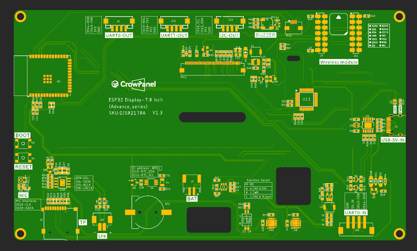
| Pin | GPIO | Labels | Status | Capabilities | Notes |
|---|---|---|---|---|---|
| 1 | 0 | IO0BOOT | strapping | - | BOOT button - hold at power-up for download mode |
| 2 | 2 | IO2MIC_WS | safe | - | I2S microphone word select - also routed to the wireless module socket |
| 3 | 3 | IO3LCD_R | strapping | - | Internal - RGB panel data (V1.3+ mapping) |
| 4 | 4 | IO4I2S_SDINSD_MISO | safe | spi | Function-switched - speaker I2S data or microSD MISO, selected by S0/S1; also on the module socket |
| 5 | 5 | IO5I2S_BCLKSD_CLK | safe | spi | Function-switched - speaker I2S bit clock or microSD clock, selected by S0/S1; also on the module socket |
| 6 | 6 | IO6I2S_LRCLKSD_MOSI | safe | spi | Function-switched - speaker I2S word clock or microSD MOSI, selected by S0/S1; also on the module socket |
| 7 | 7 | IO7LCD_R | safe | - | Internal - RGB panel data |
| 8 | 8 | IO8BUZZER | safe | - | Passive buzzer on V1.0 (moved behind the STC8 helper on V1.2+); also routed to the module socket |
| 9 | 9 | IO9LCD_G | strapping | - | Internal - RGB panel data |
| 10 | 10 | IO10LCD_G | strapping | - | Internal - RGB panel data |
| 11 | 11 | IO11LCD_G | strapping | - | Internal - RGB panel data |
| 12 | 12 | IO12LCD_G | strapping | - | Internal - RGB panel data |
| 13 | 13 | IO13LCD_G | strapping | - | Internal - RGB panel data |
| 14 | 14 | IO14LCD_G | strapping | - | Internal - RGB panel data |
| 15 | 15 | IO15SDA | safe | i2c | I2C-OUT port - shared with GT911 touch, PCF8563 RTC (0x51) and the STC8 backlight controller (0x30 on V1.2+); add devices, don't repurpose |
| 16 | 16 | IO16SCL | safe | i2c | I2C-OUT port - same shared bus as IO15 |
| 17 | 17 | IO17LCD_R | safe | - | Internal - RGB panel data |
| 18 | 18 | IO18LCD_R | safe | - | Internal - RGB panel data |
| 19 | 19 | IO19UART1_RXMIC_CLK | uart | uart | Function-switched - UART1-OUT port or I2S microphone clock; also on the module socket |
| 20 | 20 | IO20UART1_TXMIC_DATA | uart | uart | Function-switched - UART1-OUT port or I2S microphone data; also on the module socket |
| 21 | 21 | IO21LCD_B | safe | - | Internal - RGB panel data |
| 22 | 38 | IO38LCD_B | safe | - | Internal - RGB panel data |
| 23 | 39 | IO39LCD_PCLK | strapping | - | Internal - RGB panel pixel clock (20MHz, V1.3+ mapping) |
| 24 | 40 | IO40LCD_HSYNC | strapping | - | Internal - RGB panel horizontal sync |
| 25 | 41 | IO41LCD_VSYNC | strapping | - | Internal - RGB panel vertical sync |
| 26 | 42 | IO42LCD_DE | strapping | - | Internal - RGB panel data enable |
| 27 | 43 | IO43TXD0 | uart | uart | UART0 - CH340K USB-C flashing/logs, also on the UART0-OUT and UART0-IN ports |
| 28 | 44 | IO44RXD0 | uart | uart | UART0 - CH340K USB-C flashing/logs, also on the UART0-OUT and UART0-IN ports |
| 29 | 45 | IO45LCD_B | strapping | - | Internal - RGB panel data |
| 30 | 46 | IO46LCD_R | strapping | - | Internal - RGB panel data |
| 31 | 47 | IO47LCD_B | strapping | - | Internal - RGB panel data |
| 32 | 48 | IO48LCD_B | strapping | - | Internal - RGB panel data |
Start with these
12 pins with no boot or system involvementFreely assignable - no strapping, flash, USB or JTAG duties. Ideal first picks for buttons, sensors and LEDs.
Fine - with a little care
18 pins · 12 things to knowIO0 Bootstrapping pin (Chip boot mode selection) Strapping
Must be pulled high (default) or low (to enter UART download mode) at reset. Using it for other functions can interfere with boot mode configuration.
IO3 Bootstrapping pin (controls JTAG signal source) Strapping
Sampled at reset to select JTAG interface (USB Serial/JTAG controller vs. external pins). Improper use can disable external JTAG or alter debug interface.
IO9IO10IO11IO12IO13IO14 General-purpose SPI2 (FSPI) IO MUX pins Other
IO MUX pin of the general-purpose SPI2 (FSPI) bus, not of the in-package flash - that sits on GPIO26-32. The datasheet lists it as a priority-2 pin ("can be freely used without restrictions"), so it is only taken if your board wires flash, an SD card or a display to FSPI.
- IO9General-purpose SPI2 (FSPI) IO MUX pin - hold/data line (FSPIHD)
- IO10General-purpose SPI2 (FSPI) IO MUX pin - chip select (FSPICS0)
- IO11General-purpose SPI2 (FSPI) IO MUX pin - data in (FSPID)
- IO12General-purpose SPI2 (FSPI) IO MUX pin - clock (FSPICLK)
- IO13General-purpose SPI2 (FSPI) IO MUX pin - data out (FSPIQ)
- IO14General-purpose SPI2 (FSPI) IO MUX pin - write-protect/data line (FSPIWP)
IO39 JTAG test clock (MTCK); IO MUX alternates CLK_OUT3 and SUBSPICS1 (chip select on the alternative SUBSPI memory bus, unused on standard modules) JTAG
Default JTAG TCK - keep it free if you debug over JTAG. It is not a flash or PSRAM line on standard modules: those sit on GPIO26-37.
IO40 JTAG test data out pin (MTDO) JTAG
Default JTAG TDO output for debugging. Using it as GPIO will interfere with JTAG debugging functionality.
IO41 JTAG test data in pin (MTDI) JTAG
Default JTAG TDI input for debugging. Should be reserved for JTAG or left unused if JTAG is to remain available.
IO42 JTAG test mode select pin (MTMS) JTAG
Default JTAG TMS signal for debugging. Using this pin for other purposes will disable the JTAG interface (unless JTAG is rerouted to USB).
IO43 UART0 transmit pin (U0TXD), default serial console TX UART
Used for bootloader output and UART console logs. If repurposed, you will lose the default serial output (and programming via UART0).
IO44 UART0 receive pin (U0RXD), default serial console RX UART
Used for bootloader input (download mode via serial). If repurposed, you cannot use the default UART0 download mode for programming the chip.
IO45 Bootstrapping pin (selects VDD_SPI flash voltage) Strapping
Determines flash/PSRAM power voltage (3.3 V vs 1.8 V) at boot. Must match hardware configuration; using as GPIO can upset flash supply setting.
IO46 Bootstrapping pin (used with GPIO0 for boot mode; controls ROM log output) Strapping
Must be at a defined level during reset (with GPIO0) to select normal or download boot and UART/USB print mode. This pin is input-only (no output drive), so it should be left for its intended strapping function.
IO47IO48 Octal SPI differential clock legs (SPICLK_P/N_DIFF), used only by the 1.8 V octal flash/PSRAM variants Other
Only the 1.8 V octal parts (ESP32-S3R8V, ESP32-S3R16V) run the differential memory clock here, and on those the pin works at 1.8 V instead of 3.3 V. On the common 3.3 V modules it is a normal GPIO - several devkits drive their RGB LED from GPIO48.
- IO47Octal SPI differential clock positive leg (SPICLK_P_DIFF), used only by the 1.8 V octal flash/PSRAM variants
- IO48Octal SPI differential clock negative leg (SPICLK_N_DIFF), used only by the 1.8 V octal flash/PSRAM variants
Only if you know the tricks
2 pins · 1 thing to knowIO19IO20 USB OTG differential data pair (D- and D+) USB
By default connected to the on-chip USB Serial/JTAG controller. Using it as general GPIO without reconfiguring IO MUX will interfere with USB functionality.
- IO19USB OTG negative differential data line (USB_D-)
- IO20USB OTG positive differential data line (USB_D+)
All 32 pins on the Elecrow CrowPanel Advance 7.0 (ESP32-S3) are usable GPIO.
Peripheral wiring is straightforward: I²C is mapped to SDA on GPIO15 and SCL on GPIO16.
18 of the exposed pins carry boot-time or system duties on the ESP32-S3 (IO0, IO3, IO9 and 15 more) - check the guidance above before wiring anything to them. IO2, IO4, IO5, IO6 and 8 more are free of any such role - the safest first picks.
Pinout notes Like every RGB-panel ESP32-S3 board, most pins drive the display: 16 data lines plus DE on IO42, HSYNC/VSYNC on IO40/IO41 and PCLK on IO39 (V1.3+ mapping).…
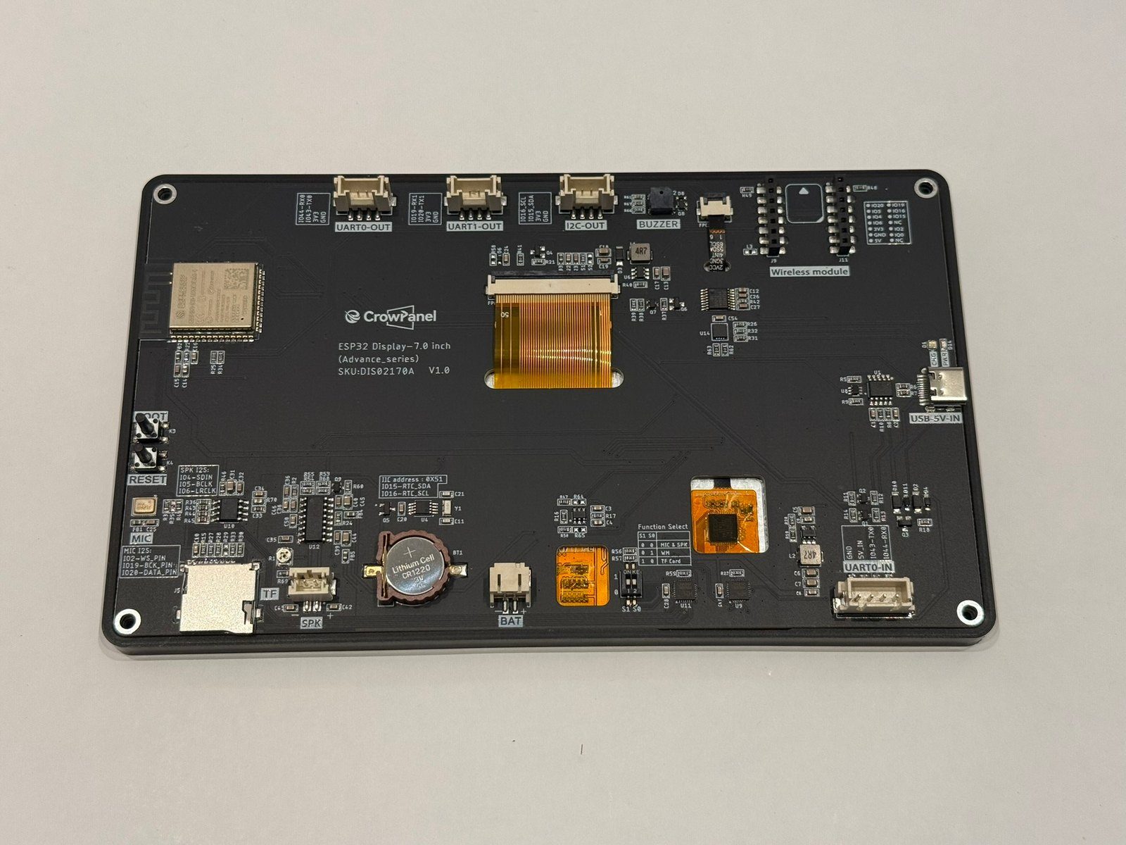
Like every RGB-panel ESP32-S3 board, most pins drive the display: 16 data lines plus DE on IO42, HSYNC/VSYNC on IO40/IO41 and PCLK on IO39 (V1.3+ mapping). Your I/O comes through the ports on the back: UART0-OUT on IO43/IO44 (shared with the CH340K USB-C flashing path, and duplicated on the 5V-input UART0-IN port), UART1-OUT on IO19/IO20, and I2C-OUT on IO15/IO16.
The shared pins are the thing to internalize. IO4/IO5/IO6 carry speaker I2S or the microSD card; IO19/IO20 carry UART1 or the I2S microphone; and the wireless module socket wants IO2, IO4-IO6, IO8, IO15/IO16 and IO19/IO20 depending on the module. The S0/S1 function switches on the back select between MIC&SPK, wireless module and TF card modes - the valid combinations are printed next to the switches, and they differ slightly between hardware revisions.
The I2C bus on IO15/IO16 is shared with the GT911 touch controller, the PCF8563 RTC (address 0x51) and the STC8 helper MCU that handles the backlight (address 0x30 on V1.2+) - extend it, don't repurpose it. IO0 is the BOOT button, and IO8 drives the passive buzzer on V1.0 (later revisions moved it behind the STC8).
Getting started
flash your first firmware in ~2 minutesBoard: ESP32S3 Dev Module Flash Size: 16MB (128Mb) PSRAM: OPI PSRAM Partition Scheme: 16M Flash (3MB APP/9.9MB FATFS) Upload Speed: 921600
// toggle GPIO2 - wire an LED and resistor to it
void setup() {
  pinMode(2, OUTPUT);
}
void loop() {
  digitalWrite(2, HIGH); delay(500);
  digitalWrite(2, LOW);  delay(500);
}[env:elecrow-crowpanel-advance-7-esp32-s3]
platform = espressif32
board = esp32-s3-devkitc-1
framework = arduino
monitor_speed = 115200
upload_speed = 921600
board_build.arduino.memory_type = qio_opi
build_flags = -DBOARD_HAS_PSRAMesp32-s3-devkitc-1 - or type it after board =.esp32:
board: esp32-s3-devkitc-1
variant: esp32s3
framework:
type: esp-idf
psram:
mode: octal
speed: 80MHz
# blink - GPIO2
output:
- platform: gpio
pin: 2
id: led_out
light:
- platform: binary
name: "LED"
output: led_outesp32-s3-devkitc-1 (same ids as PlatformIO).esptool.py --chip esp32s3 --port /dev/ttyACM0 \
--baud 921600 write_flash 0x0 firmware.bin--port = your /dev/tty* (macOS/Linux) or COMx (Windows).Good to know
board-specific quirks worth 60 seconds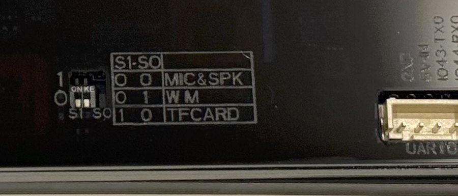
The S3 doesn't have enough free GPIO to run audio, microSD and a radio module simultaneously, so Elecrow multiplexes them: IO4-IO6 and IO19/IO20 are routed by the S0/S1 function switches on the back. The valid combinations (mic&speaker / wireless module / TF card) are printed right next to the switches. If the SD card, microphone or radio module "died" after you changed something else, check the switch…
The S3 doesn't have enough free GPIO to run audio, microSD and a radio module simultaneously, so Elecrow multiplexes them: IO4-IO6 and IO19/IO20 are routed by the S0/S1 function switches on the back. The valid combinations (mic&speaker / wireless module / TF card) are printed right next to the switches.
If the SD card, microphone or radio module "died" after you changed something else, check the switch position before debugging code - one of us lost an evening to this.
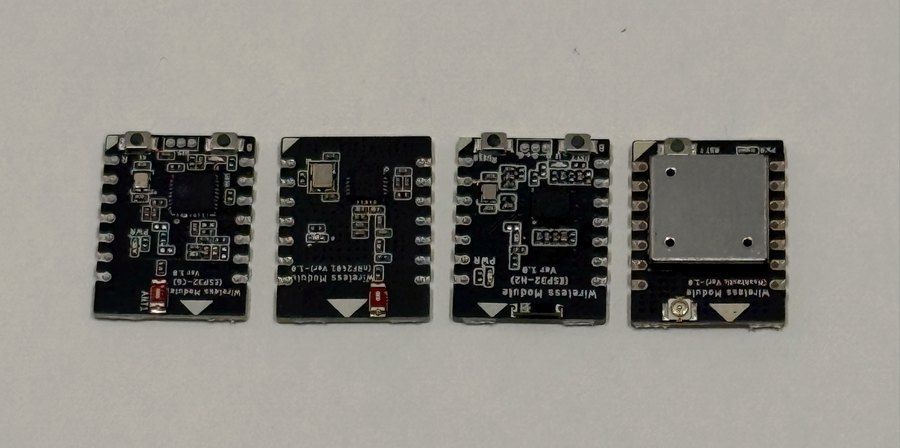
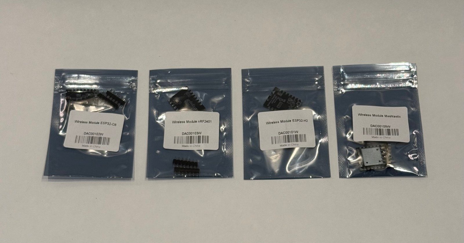
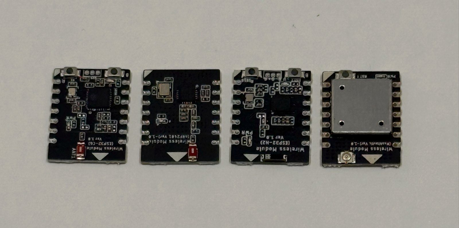
The socket on the back takes Elecrow's plug-in radios: ESP32-H2 for Zigbee/Thread, ESP32-C6 for Wi-Fi 6, nRF2401 for cheap 2.4 GHz links, and a Meshtastic LoRa module. We tested all four in our review - integration is genuinely plug-in plus sample code, with the DIP switches set to WM mode. The Meshtastic module is the sleeper feature - it turns the panel into a mesh node with a 7" touchscreen, something the…
The socket on the back takes Elecrow's plug-in radios: ESP32-H2 for Zigbee/Thread, ESP32-C6 for Wi-Fi 6, nRF2401 for cheap 2.4 GHz links, and a Meshtastic LoRa module. We tested all four in our review - integration is genuinely plug-in plus sample code, with the DIP switches set to WM mode.
The Meshtastic module is the sleeper feature - it turns the panel into a mesh node with a 7" touchscreen, something the Meshtastic ecosystem otherwise lacks.
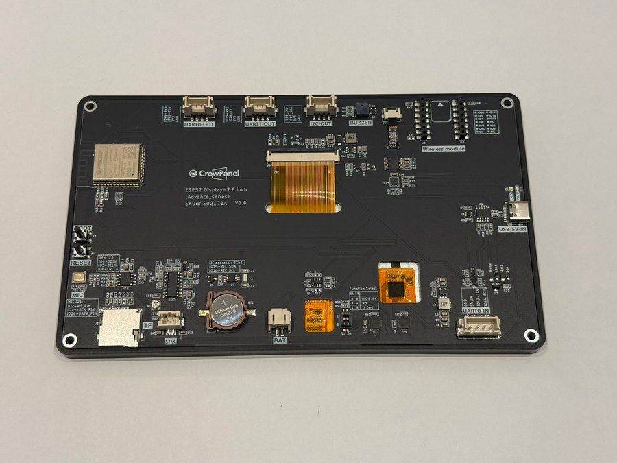
On V1.2 and later, backlight brightness, touch reset and amplifier mute are handled by an STC8 microcontroller at I2C address 0x30 - you write one byte (0 = brightest, 245 = off) instead of driving a PWM pin. V1.0 boards used a PCA9557 GPIO expander instead. Firmware must poke the right mechanism for the revision, which is why Elecrow's examples come in per-version folders. A running firmware with a black…
On V1.2 and later, backlight brightness, touch reset and amplifier mute are handled by an STC8 microcontroller at I2C address 0x30 - you write one byte (0 = brightest, 245 = off) instead of driving a PWM pin. V1.0 boards used a PCA9557 GPIO expander instead. Firmware must poke the right mechanism for the revision, which is why Elecrow's examples come in per-version folders.
A running firmware with a black screen usually means the backlight write went to the wrong address for your revision - it's not a dead panel.
Gallery
8 photos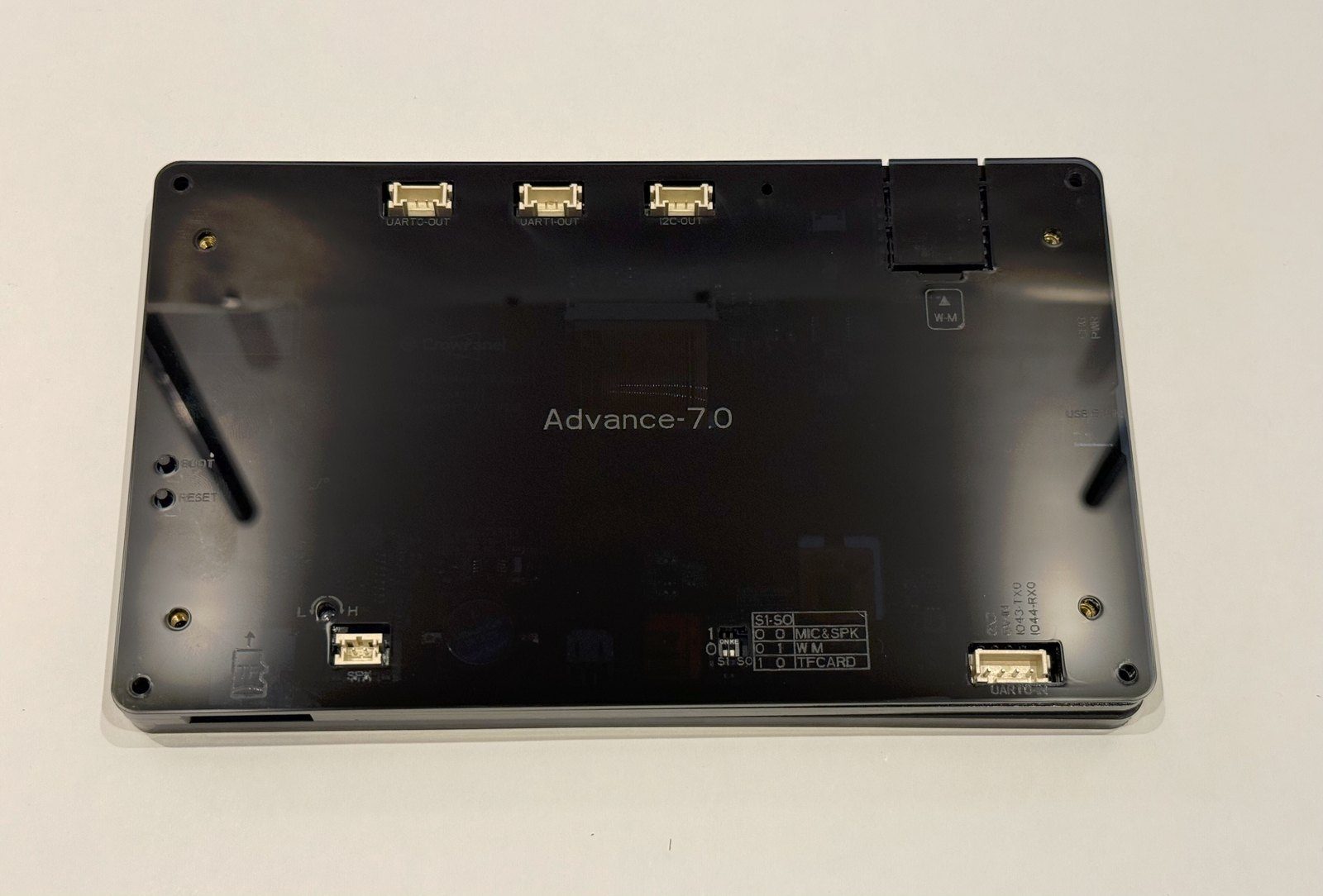
Specifications
ESP32-S3 · vs other ESP32 chips →About this board
Inside sits the ESP32-S3 - a dual-core Xtensa with vector extensions suited to AI workloads.
At $34.90 it's on the expensive side for an ESP32-S3 board - most land around $29.
With 32 GPIO broken out, you get more pins to play with than most ESP32-S3 boards offer.
Around the module: 8MB (OPI) PSRAM, an IPS LCD 7.0" 800x480 display with touch, a microSD slot, a microphone (I2S MEMS), a speaker, a speaker connector (PH2.0-2P), an amplifier (NS4168), a PCF8563 RTC, a buzzer, battery charging (TP4059) via PH2.0-2P and Boot/Reset buttons.
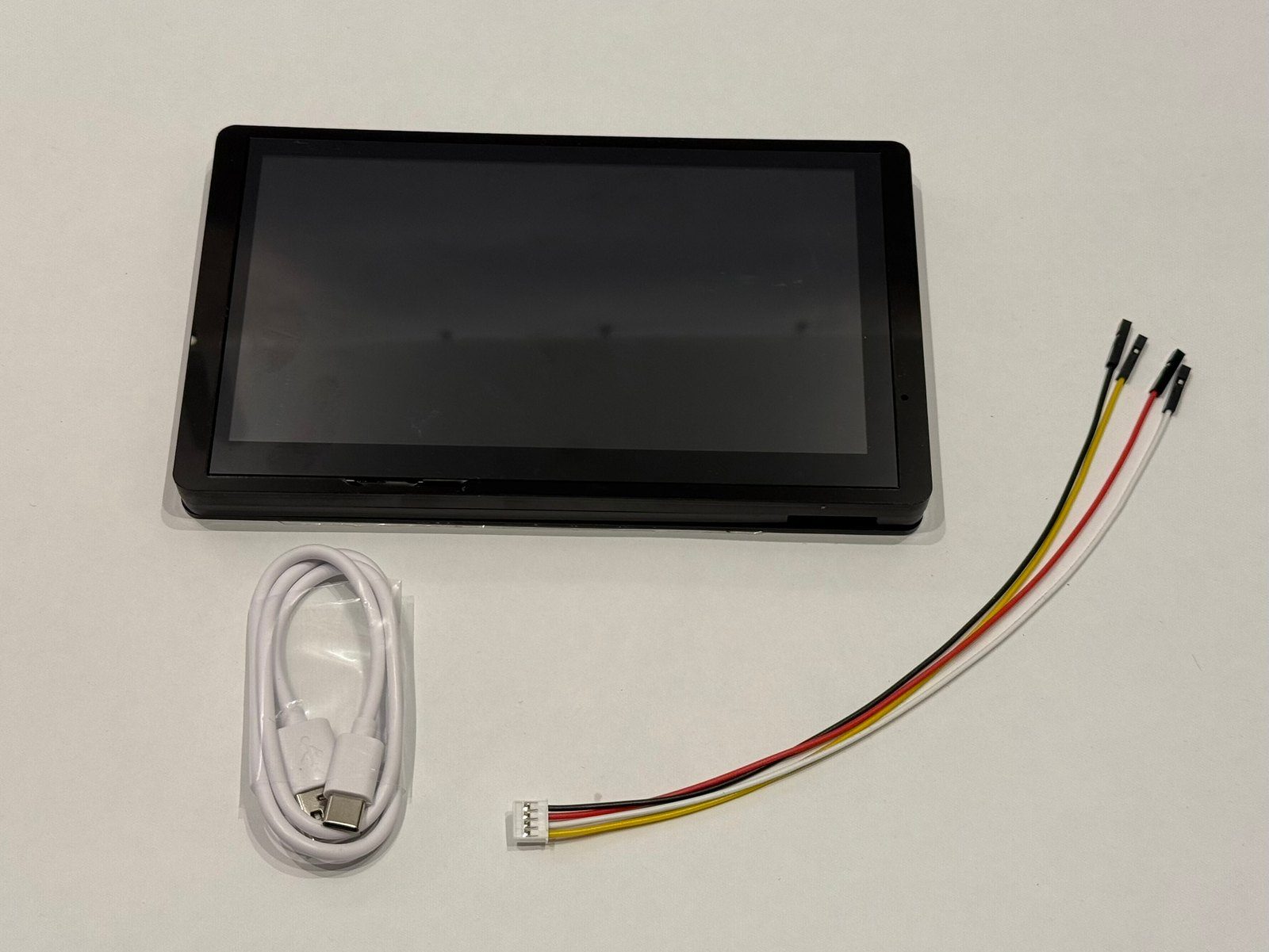
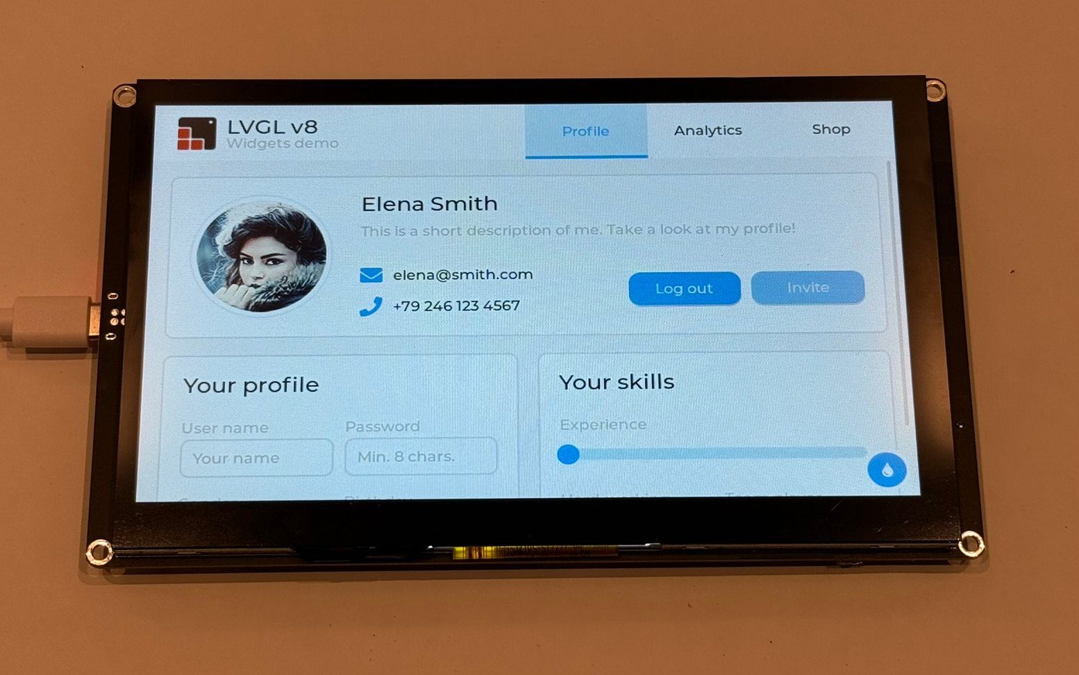
The Elecrow CrowPanel Advance 7.0 is the board that defined the Advance formula, and one we know first-hand - we reviewed it in full, including the plug-in radio modules. It pairs a 7-inch 800x480 IPS capacitive touchscreen with an ESP32-S3-WROOM-1 N16R8 (dual-core LX7 at 240 MHz, 16 MB flash, 8 MB octal PSRAM), which is enough to run reasonably fluid LVGL interfaces at this resolution - just don't expect miracles when animations get heavy.
What separates it from the sea of generic ESP32 display boards is the housekeeping around the screen: a PCF8563 RTC with coin-cell backup, an I2S microphone and NS4168-amplified speaker output, a passive buzzer, battery connector with TP4059 charging, and the swappable wireless module socket. In our review we plugged in the ESP32-H2 (Zigbee/Thread), ESP32-C6 (Wi-Fi 6), nRF2401 and Meshtastic LoRa modules - all worked with Elecrow's sample code, and the Meshtastic option in particular turns the panel into a ready-made mesh node with a big screen.
The catch you should understand before buying: the S3 doesn't have enough pins for all of this at once, so two DIP switches on the back multiplex the I2S audio, microSD and wireless module functions onto the same GPIO. Mic + speaker, radio module, or TF card - pick the combination the switch table allows, not all three.
Elecrow has revved this board through several hardware versions (V1.0 to V1.5) with real behavioral differences - the backlight moved from a GPIO expander to an STC8 helper MCU on I2C, and the ESPHome examples are split by revision. It's a mature, well-documented HMI at a fair price; our review unit was a V1.0 and the experience out of the box was genuinely good. If you need more headroom than the S3 can give, its successor is the CrowPanel Advance ESP32-P4 line.
- 7" 800x480 IPS panel with 178-degree viewing angles and GT911 capacitive multi-touch, driven over a 16-bit RGB parallel bus
- ESP32-S3-WROOM-1 N16R8 module - 16 MB flash, 8 MB octal PSRAM
- Swappable wireless module socket - optional ESP32-H2 (Zigbee/Thread), ESP32-C6 (Wi-Fi 6), nRF2401 and Meshtastic LoRa modules (all four tested in our review)
- PCF8563 RTC (I2C 0x51) with CR1220 coin-cell backup for timekeeping through power loss
- I2S MEMS microphone plus NS4168-amplified speaker output (PH2.0 connector) and a passive buzzer
- S0/S1 function switches multiplex mic/speaker, wireless module and microSD onto the shared GPIO
- Crowtail-style UART0, UART1 and I2C ports on HY2.0-4P connectors
- PH2.0 battery connector with TP4059 charging; UART0-IN port doubles as a 5V power input
- STC8 helper MCU (I2C 0x30 on V1.2+) controls backlight brightness, touch reset and amplifier mute
- USB-C flashing and logs via CH340K; Boot and Reset buttons
- Multiple hardware revisions (V1.0-V1.5) with per-revision ESPHome examples
FAQ
6 common questionsDoes the CrowPanel Advance 7.0 work with ESPHome?›
Which hardware revision will I get, and does it matter?›
Can I use the microphone, speaker, SD card and a radio module at the same time?›
How does it compare to the non-Advance CrowPanel 7.0?›
Does the Meshtastic module really work with it?›
How do I flash it?›
Where to buy
prices are typical street pricesResources
Similar boards

