
Elecrow CrowPanel E-Paper 5.79 (ESP32-S3)
5.79" 792x272 black-and-white e-paper on an ESP32-S3 N8R8 with a rotary switch, buttons and a 2x10 GPIO header - we reviewed it and later wrote the ESPHome/LVGL driver for it.

Elecrow CrowPanel E-Paper 5.79 (ESP32-S3) Pinout
25 pins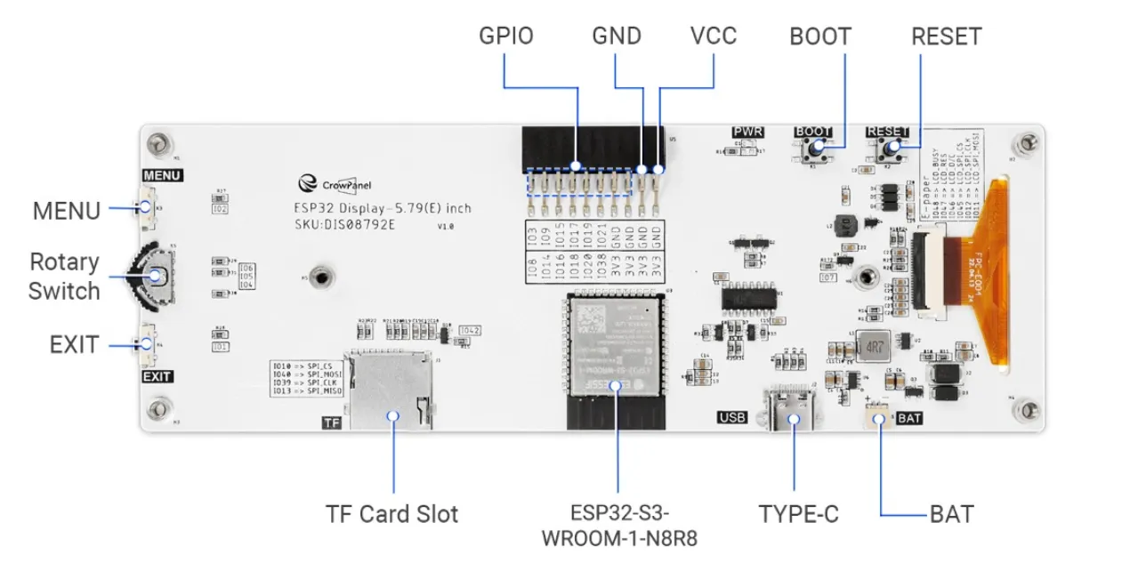
| Pin | GPIO | Labels | Status | Capabilities | Notes |
|---|---|---|---|---|---|
| 1 | 0 | IO0BOOT | strapping | - | BOOT button - hold at power-up for download mode |
| 2 | 1 | IO1EXIT_BTN | safe | - | Exit button - active low |
| 3 | 2 | IO2MENU_BTN | safe | - | Menu button - active low |
| 4 | 3 | IO3HDR | strapping | - | Free GPIO on the 2x10 header |
| 5 | 4 | IO4ROTARY_DOWN | safe | - | Rotary switch down - active low |
| 6 | 5 | IO5ROTARY_PRESS | safe | - | Rotary switch press - active low |
| 7 | 6 | IO6ROTARY_UP | safe | - | Rotary switch up - active low |
| 8 | 7 | IO7EPD_POWER | safe | - | E-paper power rail switch - MUST be driven high before the display responds |
| 9 | 9 | IO9HDR | strapping | - | Free GPIO on the 2x10 header |
| 10 | 10 | IO10SD_CS | strapping | spi | microSD slot - chip select |
| 11 | 11 | IO11EPD_MOSI | strapping | spi | Internal - e-paper SPI MOSI |
| 12 | 12 | IO12EPD_CLK | strapping | spi | Internal - e-paper SPI clock |
| 13 | 13 | IO13SD_MISO | strapping | spi | microSD slot - MISO |
| 14 | 15 | IO15HDR | safe | - | Free GPIO on the 2x10 header |
| 15 | 17 | IO17HDR | safe | - | Free GPIO on the 2x10 header |
| 16 | 19 | IO19HDR | uart | - | Free GPIO on the 2x10 header |
| 17 | 21 | IO21HDR | safe | - | Free GPIO on the 2x10 header |
| 18 | 39 | IO39SD_CLK | strapping | spi | microSD slot - clock |
| 19 | 40 | IO40SD_MOSI | strapping | spi | microSD slot - MOSI |
| 20 | 43 | IO43TXD0 | uart | uart | UART0 - USB-C flashing/logs and the UART0 port |
| 21 | 44 | IO44RXD0 | uart | uart | UART0 - USB-C flashing/logs and the UART0 port |
| 22 | 45 | IO45EPD_CS | strapping | spi | Internal - e-paper chip select |
| 23 | 46 | IO46EPD_DC | strapping | - | Internal - e-paper data/command |
| 24 | 47 | IO47EPD_RST | strapping | - | Internal - e-paper reset |
| 25 | 48 | IO48EPD_BUSY | strapping | - | Internal - e-paper busy signal |
Start with these
9 pins with no boot or system involvementFreely assignable - no strapping, flash, USB or JTAG duties. Ideal first picks for buttons, sensors and LEDs.
Fine - with a little care
15 pins · 10 things to knowIO0 Bootstrapping pin (Chip boot mode selection) Strapping
Must be pulled high (default) or low (to enter UART download mode) at reset. Using it for other functions can interfere with boot mode configuration.
IO3 Bootstrapping pin (controls JTAG signal source) Strapping
Sampled at reset to select JTAG interface (USB Serial/JTAG controller vs. external pins). Improper use can disable external JTAG or alter debug interface.
IO9IO10IO11IO12IO13 General-purpose SPI2 (FSPI) IO MUX pins Other
IO MUX pin of the general-purpose SPI2 (FSPI) bus, not of the in-package flash - that sits on GPIO26-32. The datasheet lists it as a priority-2 pin ("can be freely used without restrictions"), so it is only taken if your board wires flash, an SD card or a display to FSPI.
- IO9General-purpose SPI2 (FSPI) IO MUX pin - hold/data line (FSPIHD)
- IO10General-purpose SPI2 (FSPI) IO MUX pin - chip select (FSPICS0)
- IO11General-purpose SPI2 (FSPI) IO MUX pin - data in (FSPID)
- IO12General-purpose SPI2 (FSPI) IO MUX pin - clock (FSPICLK)
- IO13General-purpose SPI2 (FSPI) IO MUX pin - data out (FSPIQ)
IO39 JTAG test clock (MTCK); IO MUX alternates CLK_OUT3 and SUBSPICS1 (chip select on the alternative SUBSPI memory bus, unused on standard modules) JTAG
Default JTAG TCK - keep it free if you debug over JTAG. It is not a flash or PSRAM line on standard modules: those sit on GPIO26-37.
IO40 JTAG test data out pin (MTDO) JTAG
Default JTAG TDO output for debugging. Using it as GPIO will interfere with JTAG debugging functionality.
IO43 UART0 transmit pin (U0TXD), default serial console TX UART
Used for bootloader output and UART console logs. If repurposed, you will lose the default serial output (and programming via UART0).
IO44 UART0 receive pin (U0RXD), default serial console RX UART
Used for bootloader input (download mode via serial). If repurposed, you cannot use the default UART0 download mode for programming the chip.
IO45 Bootstrapping pin (selects VDD_SPI flash voltage) Strapping
Determines flash/PSRAM power voltage (3.3 V vs 1.8 V) at boot. Must match hardware configuration; using as GPIO can upset flash supply setting.
IO46 Bootstrapping pin (used with GPIO0 for boot mode; controls ROM log output) Strapping
Must be at a defined level during reset (with GPIO0) to select normal or download boot and UART/USB print mode. This pin is input-only (no output drive), so it should be left for its intended strapping function.
IO47IO48 Octal SPI differential clock legs (SPICLK_P/N_DIFF), used only by the 1.8 V octal flash/PSRAM variants Other
Only the 1.8 V octal parts (ESP32-S3R8V, ESP32-S3R16V) run the differential memory clock here, and on those the pin works at 1.8 V instead of 3.3 V. On the common 3.3 V modules it is a normal GPIO - several devkits drive their RGB LED from GPIO48.
- IO47Octal SPI differential clock positive leg (SPICLK_P_DIFF), used only by the 1.8 V octal flash/PSRAM variants
- IO48Octal SPI differential clock negative leg (SPICLK_N_DIFF), used only by the 1.8 V octal flash/PSRAM variants
Only if you know the tricks
1 pins · 1 thing to knowIO19 USB OTG negative differential data line (USB_D-) USB
By default connected to the on-chip USB Serial/JTAG controller. Using it as general GPIO without reconfiguring IO MUX will interfere with USB functionality.
The Elecrow CrowPanel E-Paper 5.79 (ESP32-S3) pinout brings out 25 GPIO pins - every one of them usable in your project.
If you want zero surprises, IO1, IO2, IO4, IO5 and 5 more are free of any such role - the safest first picks. 15 of the exposed pins carry boot-time or system duties on the ESP32-S3 (IO0, IO3, IO9 and 12 more).
Pinout notes The e-paper panel takes SPI on IO12 (CLK) / IO11 (MOSI) with IO45 (CS), IO46 (DC), IO47 (RST) and IO48 (BUSY). Critically, IO7 switches the display's power…
The e-paper panel takes SPI on IO12 (CLK) / IO11 (MOSI) with IO45 (CS), IO46 (DC), IO47 (RST) and IO48 (BUSY). Critically, IO7 switches the display's power rail - it must be driven high before the panel responds at all, which catches out every first-time firmware author (our ESPHome guide handles it for you).
Physical input sits on IO2 (Menu), IO1 (Exit) and the rotary switch on IO6/IO4/IO5 (up/down/press) - all active-low with pull-ups. The microSD slot runs its own SPI on IO39 (CLK), IO40 (MOSI), IO13 (MISO), IO10 (CS).
The 2x10 header exposes power rails, the UART0 pins and six free GPIOs - IO3, IO9, IO15, IO17, IO19, IO21 - a generous allocation by display-board standards, and enough for I2C plus a handful of sensors without any bus-sharing gymnastics.
Getting started
flash your first firmware in ~2 minutesBoard: ESP32S3 Dev Module Flash Size: 8MB (64Mb) PSRAM: QSPI PSRAM Partition Scheme: 8M with spiffs (3MB APP/1.5MB SPIFFS) Upload Speed: 921600
// toggle GPIO1 - wire an LED and resistor to it
void setup() {
  pinMode(1, OUTPUT);
}
void loop() {
  digitalWrite(1, HIGH); delay(500);
  digitalWrite(1, LOW);  delay(500);
}[env:elecrow-crowpanel-epaper-5-79]
platform = espressif32
board = esp32-s3-devkitc-1
framework = arduino
monitor_speed = 115200
upload_speed = 921600
board_build.arduino.memory_type = qio_qspi
build_flags = -DBOARD_HAS_PSRAMesp32-s3-devkitc-1 - or type it after board =.esp32:
board: esp32-s3-devkitc-1
variant: esp32s3
framework:
type: esp-idf
psram:
mode: quad
speed: 80MHz
# blink - GPIO1
output:
- platform: gpio
pin: 1
id: led_out
light:
- platform: binary
name: "LED"
output: led_outesp32-s3-devkitc-1 (same ids as PlatformIO).esptool.py --chip esp32s3 --port /dev/ttyACM0 \
--baud 921600 write_flash 0x0 firmware.bin--port = your /dev/tty* (macOS/Linux) or COMx (Windows).Good to know
board-specific quirks worth 60 seconds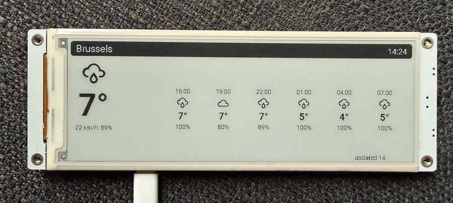
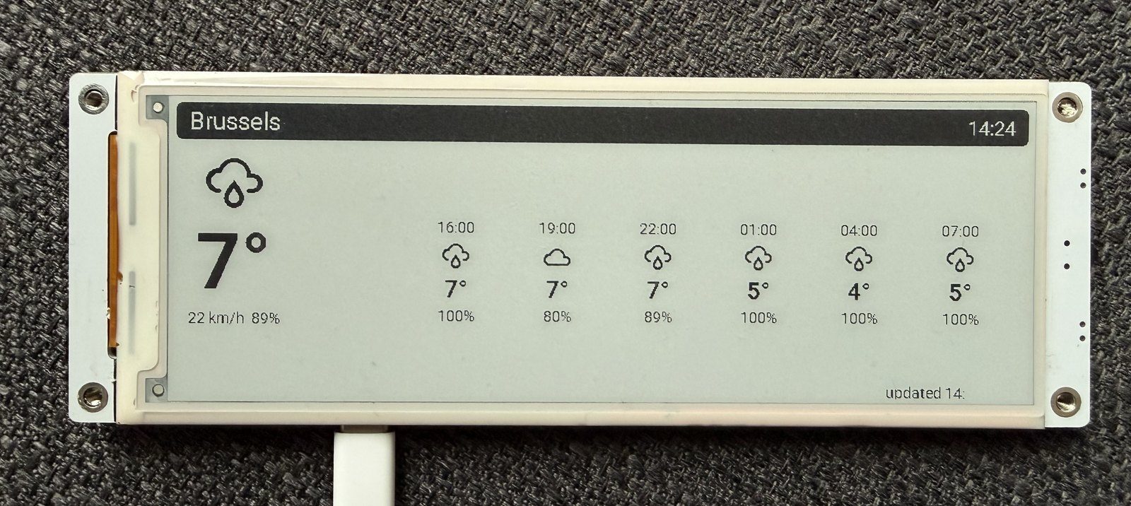
The dual-SSD1683 split panel defeats generic e-paper components, so we rewrote the driver from scratch - correct DisplayBuffer inheritance, a non-blocking update state machine, and LVGL compatibility. It's open source as crowpanel_epaper, and the guide builds a full weather dashboard on it. Set full_update_every: 10 for frequently updating dashboards, or 9999 and trigger full refreshes manually - we wire a…
The dual-SSD1683 split panel defeats generic e-paper components, so we rewrote the driver from scratch - correct DisplayBuffer inheritance, a non-blocking update state machine, and LVGL compatibility. It's open source as crowpanel_epaper, and the guide builds a full weather dashboard on it.
Set full_update_every: 10 for frequently updating dashboards, or 9999 and trigger full refreshes manually - we wire a long-press of the Menu button to force_full_update().
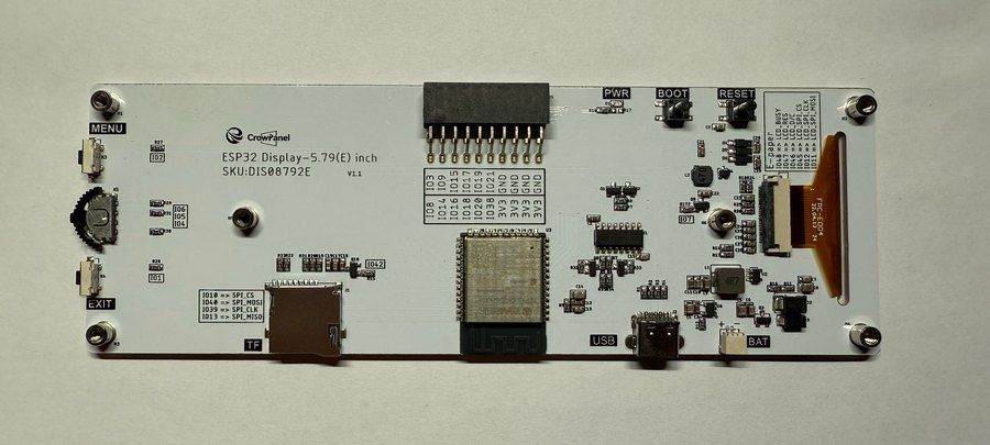
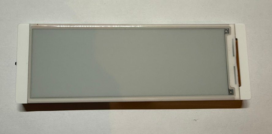
IO7 switches the e-paper's power rail. Firmware must drive it high before the first SPI transaction, or the panel stays blank and every symptom points at a wiring or driver problem that isn't there. It also means you can hard-cut display power in deep-sleep scenarios for extra savings. A blank panel with working serial logs is nearly always the IO7 rail, not a broken display - check it before opening a…
IO7 switches the e-paper's power rail. Firmware must drive it high before the first SPI transaction, or the panel stays blank and every symptom points at a wiring or driver problem that isn't there. It also means you can hard-cut display power in deep-sleep scenarios for extra savings.
A blank panel with working serial logs is nearly always the IO7 rail, not a broken display - check it before opening a support ticket.
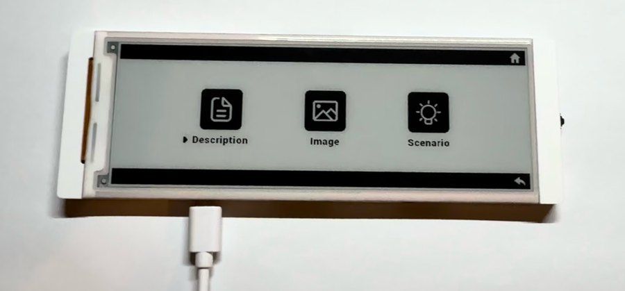
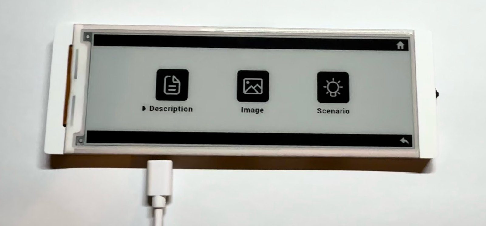
E-paper and touchscreens rarely mix, so Elecrow gave this one proper physical input: Menu (IO2), Exit (IO1) and a three-way rotary switch (IO6/IO4/IO5). Mapped as an LVGL encoder, it navigates menus surprisingly well - the preloaded demo shows the pattern.
All five inputs are active-low - configure them with pull-ups and inverted logic, as in the example configs.
Gallery
7 photos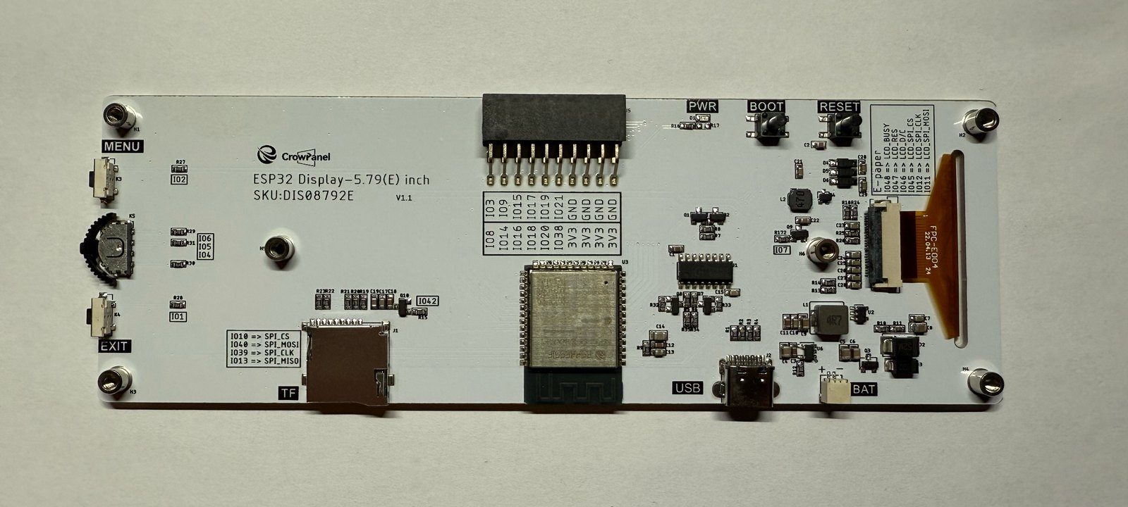
Specifications
ESP32-S3 · vs other ESP32 chips →About this board
At its core is the ESP32-S3 - a dual-core Xtensa with vector extensions suited to AI workloads.
Expect to pay about $31.90 - in line with other ESP32-S3 boards.
Onboard you'll find 8MB PSRAM, an E-Paper 5.79" 792x272 display, a microSD slot, a rotary encoder, battery charging via SH1.0-2P and Menu/Exit/Boot/Reset + rotary up/down/press buttons.
The Elecrow CrowPanel E-Paper 5.79 pairs an ESP32-S3-WROOM-1 N8R8 (8 MB flash, 8 MB PSRAM) with a wide-format 5.79-inch black-and-white e-paper panel at 792x272. We reviewed it hands-on - the short version: a well-built module in a clean acrylic case, with more physical input than e-paper boards usually get, at a price that undercuts buying a bare panel plus a dev board separately.
The input hardware is the underrated part: besides Boot and Reset you get Menu and Exit buttons plus a three-way rotary switch (up/down/press), which makes menu-driven UIs possible without any external controller. A microSD slot, battery connector with charging, UART0 port and a 2x10 GPIO header round it out - six IOs on the header are genuinely free for your own hardware.
The panel is driven by two SSD1683 controllers, each owning half of the 792-pixel width. That split design is why generic e-paper drivers don't just work - and why our review originally listed "no ESPHome support" as the main con. That con is gone: we ended up writing an ESPHome external component with full LVGL support for this exact panel, with partial refresh (~600 ms), configurable full-refresh intervals and a manual refresh hook.
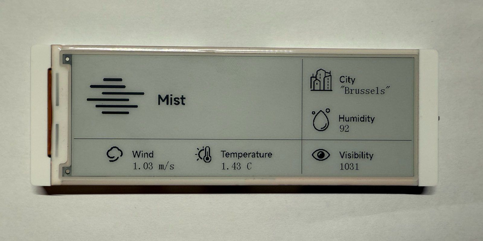
Where it fits: always-on dashboards, weather stations and status displays where an LCD's backlight and power draw are wrong, and where deep sleep between updates matters. It won't do video or smooth animation - that's e-paper physics, not a flaw - but as a low-power glanceable display with real buttons, it's one of the more complete packages around.
- 5.79" 792x272 black-and-white e-paper (two SSD1683 controllers in a split configuration)
- ESP32-S3-WROOM-1 N8R8 - 8 MB flash, 8 MB PSRAM
- Menu and Exit buttons plus a three-way rotary switch (up/down/press) for controller-free UIs
- 2x10 GPIO header with six free IOs (IO3, IO9, IO15, IO17, IO19, IO21)
- microSD slot on a dedicated SPI bus
- SH1.0 battery connector with onboard charging - built for deep-sleep battery projects
- Full ESPHome + LVGL support via our open-source crowpanel_epaper external component
- Partial refresh in ~600 ms, with configurable full-refresh cadence to clear ghosting
- Acrylic case and USB-C cable included; demo firmware preloaded
FAQ
5 common questionsDoes the CrowPanel E-Paper 5.79 work with ESPHome?›
Why does the display do nothing when I flash my own firmware?›
How fast does the screen update?›
Can it run on battery?›
What's the difference from the 4.2" CrowPanel e-paper?›
Where to buy
prices are typical street pricesResources
Similar boards

