
Elecrow ESP32 Miner LCD 2.8
Elecrow's "crypto solo miner" is really a CYD with USB-C, an acrylic case and pre-broken-out JST ports - sold as a 2-pack. We reviewed it, shelved the mining, and kept the displays.

Elecrow ESP32 Miner LCD 2.8 Pinout
25 pins| Pin | GPIO | Labels | Status | Capabilities | Notes |
|---|---|---|---|---|---|
| 1 | 0 | IO0BOOT | strapping | - | BOOT button - hold at power-up for download mode |
| 2 | 1 | IO1TXD0 | uart | uart | UART0 - CH340C USB-C flashing/logs |
| 3 | 2 | IO2TFT_DC | strapping | - | Internal - display data/command select |
| 4 | 3 | IO3RXD0 | uart | uart | UART0 - CH340C USB-C flashing/logs |
| 5 | 5 | IO5SD_CS | strapping | spi | microSD slot - chip select |
| 6 | 12 | IO12TFT_MISO | strapping | spi | Internal - display/touch SPI MISO |
| 7 | 13 | IO13TFT_MOSI | strapping | spi | Internal - display/touch SPI MOSI |
| 8 | 14 | IO14TFT_SCLK | strapping | spi | Internal - display/touch SPI clock |
| 9 | 15 | IO15TFT_CS | strapping | spi | Internal - display chip select |
| 10 | 16 | IO16UART2_RX | uart | uart | UART JST connector |
| 11 | 17 | IO17UART2_TX | uart | uart | UART JST connector |
| 12 | 18 | IO18SD_CLK | safe | spi | microSD slot - clock |
| 13 | 19 | IO19SD_MISO | safe | spi | microSD slot - MISO |
| 14 | 21 | IO21SCL | safe | i2c | I2C JST connector - SCL is IO21, SDA is IO22 on this board |
| 15 | 22 | IO22SDA | safe | i2c | I2C JST connector |
| 16 | 23 | IO23SD_MOSI | safe | spi | microSD slot - MOSI |
| 17 | 25 | IO25GPIO_ROW | safe | adc · dac | Free GPIO on the header row - ADC and DAC capable |
| 18 | 26 | IO26SPEAK | safe | dac | Speaker JST - DAC through the onboard amplifier |
| 19 | 27 | IO27TFT_BL | safe | pwm | Display backlight - IO27 here, NOT the IO21 many stock-CYD configs assume |
| 20 | 32 | IO32GPIO_ROW | safe | adc | Free GPIO on the header row - ADC capable |
| 21 | 33 | IO33TOUCH_CS | safe | spi | Internal - XPT2046 touch controller chip select |
| 22 | 34 | IO34GPIO_ROW | strapping | adc | Header row - input only |
| 23 | 35 | IO35GPIO_ROW | strapping | adc | Header row - input only |
| 24 | 36 | IO36TP_IRQ | strapping | - | Internal - XPT2046 touch interrupt (input only) |
| 25 | 39 | IO39GPIO_ROW | strapping | adc | Header row - input only |
Start with these
12 pins with no boot or system involvementFreely assignable - no strapping, flash, USB or JTAG duties. Ideal first picks for buttons, sensors and LEDs.
Fine - with a little care
13 pins · 12 things to knowIO0 Bootstrapping pin (enter bootloader when low); internal pull-up. Strapping
Must be HIGH during boot for normal startup; if held LOW on reset, forces flash programming mode.
IO1 Default UART0 TX pin for USB-serial programming and console. UART
Connected to on-board USB-UART for uploading and logs; drives serial output at boot, so using as GPIO can disrupt programming or console.
IO2 Bootstrapping pin (must be low or floating at reset); internal pull-down. Strapping
If driven HIGH on reset (while IO0 is LOW), selects an unsupported SDIO boot mode, causing boot failure.
IO3 Default UART0 RX pin for USB-serial programming (console input). UART
Used for receiving data from USB-UART (programming); also pulled HIGH at boot for console communication, so using as GPIO can disrupt uploads.
IO5 Bootstrapping pin; internal pull-up; VSPI CS0 (default SPI chip-select); acts as FSPIWP (flash write-protect) on internal-flash variants. Strapping
Must be HIGH during boot; if pulled LOW at reset, alters SDIO slave timing and may prevent normal boot.
IO12 Bootstrapping pin; JTAG TDI; sets flash voltage (VDD_SDIO); also HSPIQ (flash data line). Strapping
Keep LOW during boot (internal PD); pulling HIGH at reset selects 1.8V flash mode, causing flash brownout if 3.3V flash is used.
IO13 JTAG clock pin (TCK); also ADC2 channel 4 / Touch4 input. JTAG
Used for JTAG debugging (TCK); avoid using as GPIO if JTAG is needed.
IO14 JTAG mode select pin (TMS); also HSPI CLK and PWM-capable GPIO. JTAG
Used for JTAG debugging (TMS); driving it as GPIO may interfere with JTAG or produce spurious signals at boot.
IO15 Bootstrapping pin; JTAG TDO; controls UART0 boot log output; also HSPICS0 (secondary SPI CS). Strapping
Keep HIGH during boot (internal PU); if LOW on reset, bootloader log is silenced and boot mode may change.
IO34 Input-only GPIO (no output driver); ADC1 channel 6. Other
Cannot be used as output (no drive capability); only suitable for analog/digital input.
IO35IO39 Input-only GPIOs with ADC1 channels - no output driver Other
Cannot be used as output; only suitable for input.
- IO35Input-only GPIO (no output driver); ADC1 channel 7.
- IO39Input-only GPIO (no output); ADC1 channel 3, Hall sensor VN.
IO36 Input-only GPIO (no output); ADC1 channel 0, Hall sensor VP. Other
Cannot be used as output; only suitable for input (e.g., analog read).
All 25 pins on the Elecrow ESP32 Miner LCD 2.8 are usable GPIO.
Peripheral wiring is straightforward: I²C is mapped to SDA on GPIO22 and SCL on GPIO21.
Beyond plain digital I/O you get 5 ADC-capable pins for sensors and battery monitoring, PWM on 1 pins and 2 true DAC outputs.
13 of the exposed pins carry boot-time or system duties on the ESP32 (IO0, IO1, IO2 and 10 more) - check the guidance above before wiring anything to them. IO16, IO17, IO18, IO19 and 8 more are free of any such role - the safest first picks.
Pinout notes The display SPI matches the classic CYD recipe: IO14 (SCLK), IO13 (MOSI), IO12 (MISO), IO15 (CS), IO2 (DC), no reset pin, with the XPT2046 touch controller on…
The display SPI matches the classic CYD recipe: IO14 (SCLK), IO13 (MOSI), IO12 (MISO), IO15 (CS), IO2 (DC), no reset pin, with the XPT2046 touch controller on the same bus (IO33 CS, IO36 IRQ) and the backlight on IO27 - not IO21 as on many stock CYDs. The microSD slot gets its own SPI: IO18 (CLK), IO19 (MISO), IO23 (MOSI), IO5 (CS).
The JST connectors carry UART2 on IO16/IO17, I2C on IO22 (SDA) / IO21 (SCL), and the speaker line from DAC IO26 through the onboard amplifier. The GPIO row exposes IO25, IO32 and the input-only IO34/IO35/IO39 - the ADC-capable leftovers of a fully-committed pin budget.
Flashing runs through the CH340C on UART0 (IO1/IO3) via USB-C, with IO0 on the BOOT button. If you're porting a stock-CYD project, the only changes that usually matter are the backlight pin and the presence of real connectors where you used to solder.
Getting started
flash your first firmware in ~2 minutesBoard: ESP32 Dev Module Flash Size: 4MB (32Mb) Partition Scheme: Default 4MB with spiffs (1.2MB APP/1.5MB SPIFFS) Upload Speed: 921600
// toggle GPIO18 - wire an LED and resistor to it
void setup() {
  pinMode(18, OUTPUT);
}
void loop() {
  digitalWrite(18, HIGH); delay(500);
  digitalWrite(18, LOW);  delay(500);
}[env:elecrow-esp32-miner-2-8]
platform = espressif32
board = esp32dev
framework = arduino
monitor_speed = 115200
upload_speed = 921600esp32dev - or type it after board =.esp32:
board: esp32dev
variant: esp32
framework:
type: esp-idf
# blink - GPIO18
output:
- platform: gpio
pin: 18
id: led_out
light:
- platform: binary
name: "LED"
output: led_outesp32dev (same ids as PlatformIO).esptool.py --chip esp32 --port /dev/ttyACM0 \
--baud 921600 write_flash 0x1000 firmware.bin--port = your /dev/tty* (macOS/Linux) or COMx (Windows).Good to know
board-specific quirks worth 60 seconds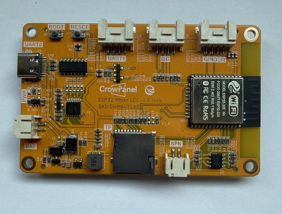
Strip the mining branding and the PCB reads like a tidied-up ESP32-2432S028R: same chip, same ILI9341 SPI wiring, same resistive touch. The additions are around the edge - JST connectors for I2C, two UARTs, battery and speaker, where a stock CYD offers solder pads under the bezel. Porting a CYD project? Everything transfers except the backlight - it's IO27 here, not IO21. That one pin is the entire migration…
Strip the mining branding and the PCB reads like a tidied-up ESP32-2432S028R: same chip, same ILI9341 SPI wiring, same resistive touch. The additions are around the edge - JST connectors for I2C, two UARTs, battery and speaker, where a stock CYD offers solder pads under the bezel.
Porting a CYD project? Everything transfers except the backlight - it's IO27 here, not IO21. That one pin is the entire migration guide.
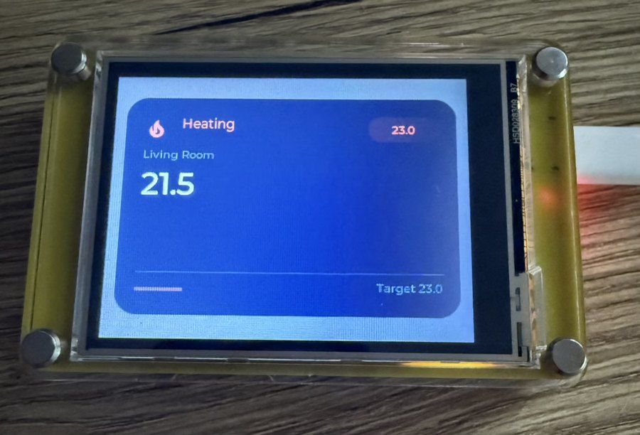
Our review walks through both firmware paths - a TFT_eSPI User_Setup for Arduino IDE and a minimal ESP-IDF project pulling the official ILI9341 driver from the component registry. Either way you're minutes from a working 320x240 UI, and the LVGL ecosystem treats it as the known quantity it is.
Keep the TFT SPI at 16MHz to start - this panel tolerates 27MHz on short traces, but 16 is the no-surprises setting.
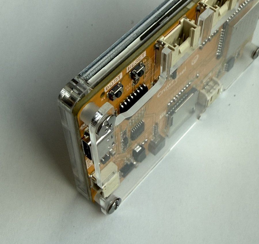
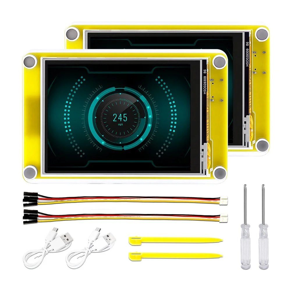
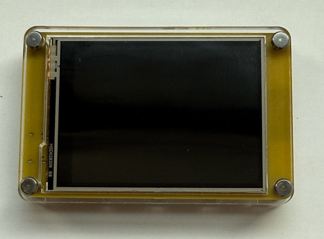
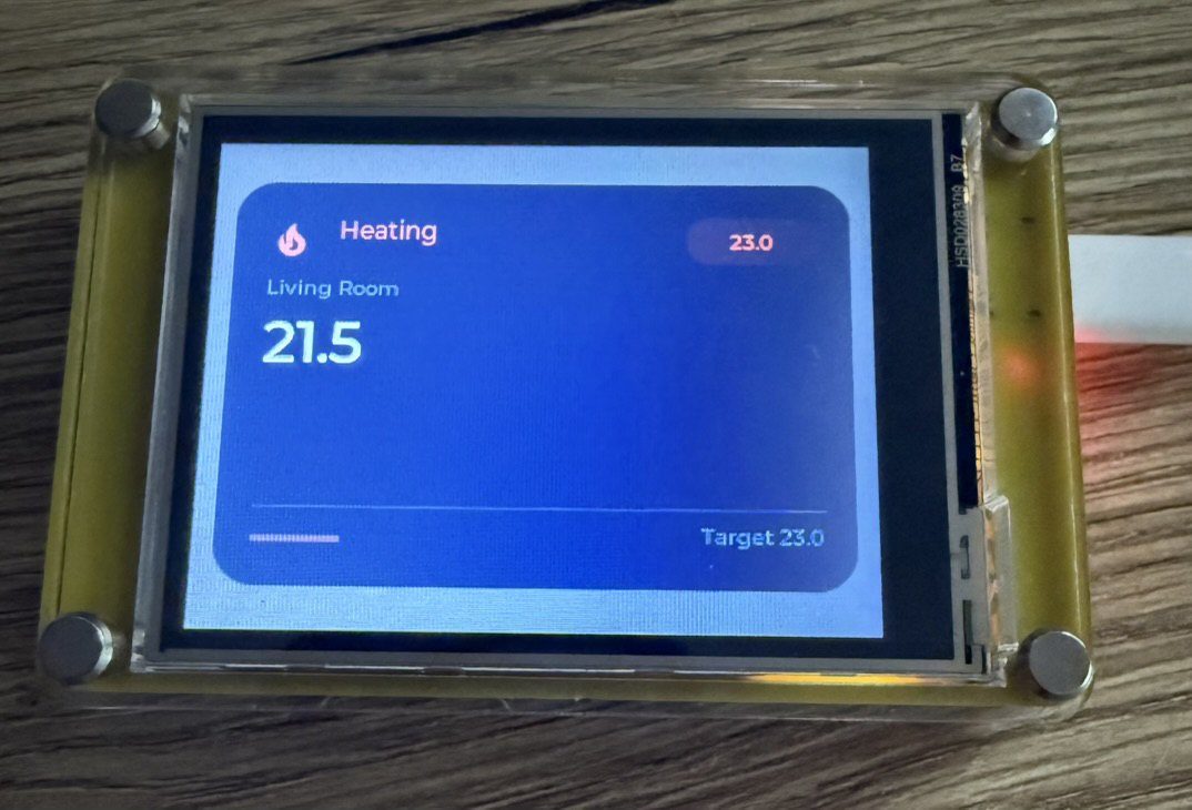
An acrylic sandwich case ships in the box - not premium, but it means the board can sit on a desk or be handed to someone non-technical from day one. Stock CYDs arrive as bare PCBs, and a case is the first thing most people end up sourcing anyway.
The battery JST sits under the case - route the cable before final assembly if you're going portable.
Gallery
6 photos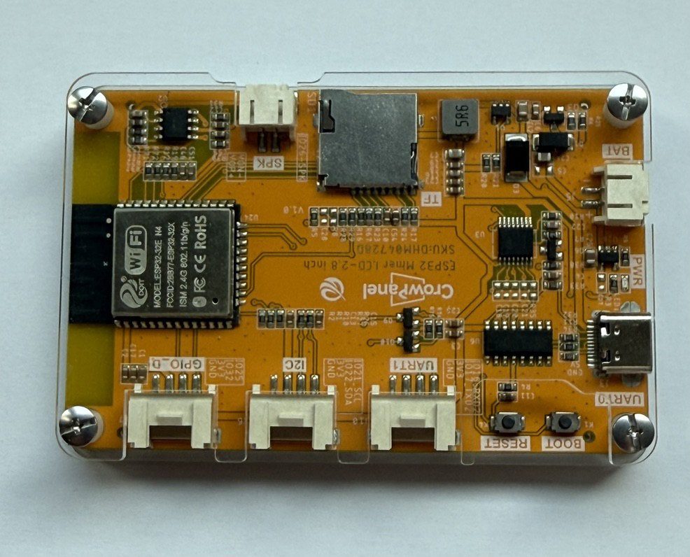
Specifications
ESP32 · 85.7 × 57 mm · vs other ESP32 chips →Dimensions
About this board
Inside sits the ESP32 - a dual-core Xtensa with both Bluetooth Classic and BLE. Sibling CYD boards cover the ESP32-S3 and ESP32-C3, so you can change radios or horsepower without changing the footprint.
At $29.90 it's on the expensive side for a CYD board - most land around $22.
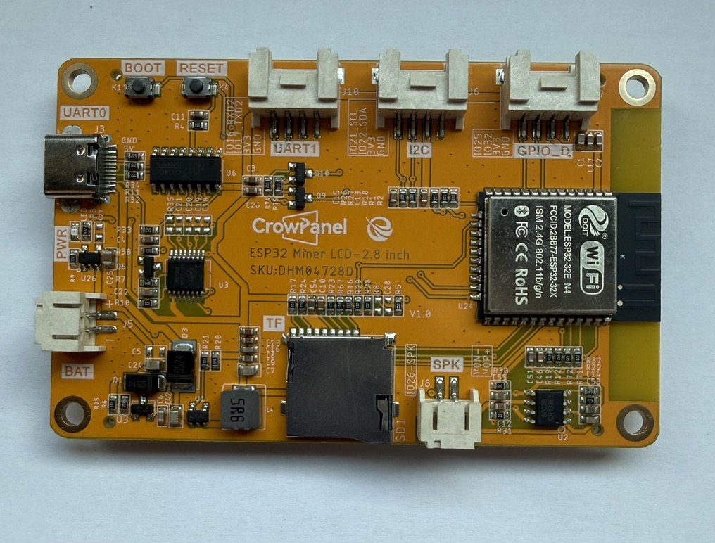
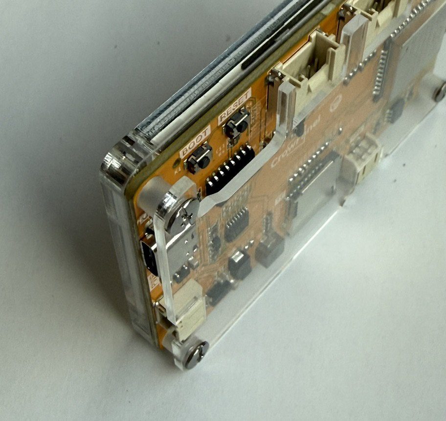
Around the module: a TFT LCD (TN) 2.8" 320x240 display with touch, a microSD slot, a speaker, a speaker connector (PH2.0-2P), battery charging via PH2.0-2P and Boot/Reset buttons.
The Elecrow ESP32 Miner LCD ships in a box that says Cryptocurrency Solo Miner with 1000 KH/s Hashrate. In our review we dutifully flashed NMMiner, watched shares scroll by, and then did what most owners will do: shelved the mining idea and kept the hardware - because underneath, this is a Cheap Yellow Display with the rough edges filed off.
The spec sheet is pure CYD: ESP32-WROOM-32-N4, 2.8-inch 320x240 ILI9341V TN panel, XPT2046 resistive touch with an included stylus, 4 MB flash and no PSRAM. What Elecrow adds is convenience - USB-C instead of micro-USB, an acrylic sandwich case in the box, and pre-terminated JST connectors (I2C, two UARTs, battery, speaker) plus a microSD slot and a GPIO row, where a stock CYD gives you solder pads.
Being honest, as our review was: if you already own a stock CYD, nothing here justifies replacing it - the panel is the same TN part with the same viewing angles, and the chip is identical. The pitch is for new purchases: at roughly $15 per unit (sold as a 2-pack only), you're paying CYD money and getting connectors, a case and USB-C that you'd otherwise bodge on yourself.
Firmware-wise it behaves exactly like the CYD it is - our review includes ready-to-paste TFT_eSPI and ESP-IDF starter configs. The one trap: the backlight is on IO27, not the IO21 many stock-CYD configs assume, so a "dark screen after flashing" is almost always that one pin number.
- Functionally a CYD - ESP32-WROOM-32-N4, 2.8" 320x240 ILI9341V TN panel, XPT2046 resistive touch, stylus included
- USB-C via CH340C instead of the typical CYD micro-USB
- Pre-terminated JST connectors - I2C, 2x UART, battery (3.7-4.2V with charging) and speaker
- microSD slot on a dedicated SPI bus, plus a GPIO row (IO25, IO32, IO34/35/39)
- Acrylic sandwich case included in the box
- Ships as a 2-pack (~$15 per unit) with mining firmware preloaded - reflash it like any ESP32
- TFT_eSPI and ESP-IDF starter configs published in our review
- -20 to 70 degrees C rated; 85.7 x 57 mm board
FAQ
5 common questionsIs it actually any good as a crypto miner?›
How is it different from a regular Cheap Yellow Display?›
Can I flash it with my existing CYD firmware or ESPHome config?›
Why does it only come as a 2-pack?›
Does the touchscreen work like a CYD's too?›
Where to buy
prices are typical street pricesResources
Similar boards
All Cyd boards →

