
ESP32S2 Dev Module
Breadboard-friendly ESP32-S2 board with native USB and full Wi-Fi support - ideal for general-purpose IoT development.

ESP32S2 Dev Module Pinout
26 pins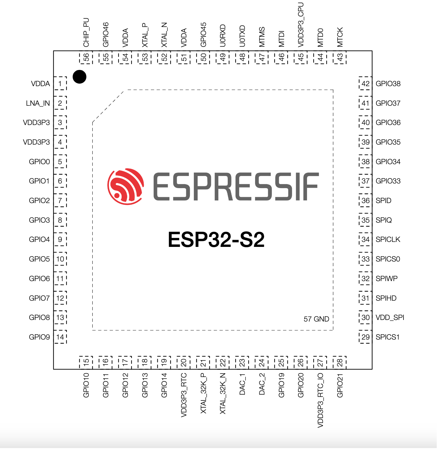
| Pin | GPIO | Labels | Status | Capabilities | Notes |
|---|---|---|---|---|---|
| 1 | 1 | A0T1PWM | safe | adc · touch | |
| 2 | 2 | A1T2PWM | safe | adc · touch | |
| 3 | 3 | A2T3PWM | safe | adc · touch | |
| 4 | 4 | A3T4PWM | safe | adc · touch | |
| 5 | 5 | A4T5PWM | safe | adc · touch | |
| 6 | 6 | A5T6PWM | safe | adc · touch | |
| 7 | 7 | A6T7PWM | safe | adc · touch | |
| 8 | 8 | SDAA7T8PWM | safe | adc · touch · i2c | |
| 9 | 9 | SCLA8T9PWM | strapping | adc · touch · i2c | |
| 10 | 10 | A9T10PWM | strapping | adc · touch | |
| 11 | 11 | A10T11PWM | strapping | adc · touch | |
| 12 | 12 | A11T12PWM | strapping | adc · touch | |
| 13 | 13 | A12T13PWM | strapping | adc · touch | |
| 14 | 14 | A13T14PWM | strapping | adc · touch | |
| 15 | 15 | A14PWM | strapping | adc | |
| 16 | 16 | A15PWM | strapping | adc | |
| 17 | 17 | A16DAC1PWM | safe | adc · dac | |
| 18 | 18 | LED_BUILTINA17DAC2PWM | safe | adc · dac | |
| 19 | 19 | A18PWM | uart | adc | |
| 20 | 20 | A19PWM | uart | adc | |
| 21 | 34 | SSPWM | safe | spi | |
| 22 | 35 | MOSIPWM | safe | spi | |
| 23 | 36 | SCKPWM | safe | spi | |
| 24 | 37 | MISOPWM | safe | spi | |
| 25 | 43 | TXPWM | uart | uart | |
| 26 | 44 | RXPWM | uart | uart |
Start with these
16 pins with no boot or system involvementFreely assignable - no strapping, flash, USB or JTAG duties. Ideal first picks for buttons, sensors and LEDs.
Fine - with a little care
8 pins · 3 things to knowSCLGPIO9A9GPIO10A10GPIO11A11GPIO12A12GPIO13A13GPIO14 General-purpose SPI2 (FSPI) IO MUX pins Other
IO MUX pin of the general-purpose SPI2 (FSPI) bus, not of the in-package flash - that sits on GPIO26-32. The datasheet does not restrict it, so it is only taken if your board wires flash, an SD card or a display to FSPI.
- SCLGeneral-purpose SPI2 (FSPI) IO MUX pin - hold/data line (FSPIHD)
- A9General-purpose SPI2 (FSPI) IO MUX pin - chip select (FSPICS0)
- A10General-purpose SPI2 (FSPI) IO MUX pin - data in (FSPID)
- A11General-purpose SPI2 (FSPI) IO MUX pin - clock (FSPICLK)
- A12General-purpose SPI2 (FSPI) IO MUX pin - data out (FSPIQ)
- A13General-purpose SPI2 (FSPI) IO MUX pin - write-protect/data line (FSPIWP)
A14GPIO15 32.768 kHz RTC crystal oscillator positive input (XTAL_32K_P); also functions as GPIO15 (U0RTS, ADC2_CH4). Other
If an external 32 kHz crystal is used for RTC, this pin is dedicated to the crystal and cannot be used as GPIO.
A15GPIO16 32.768 kHz RTC crystal negative input (XTAL_32K_N); also GPIO16 (U0CTS, ADC2_CH5). Other
If using an external 32 kHz crystal, this pin is connected to the crystal and should not be used as general I/O.
Only if you know the tricks
2 pins · 2 things to knowA18GPIO19 USB OTG D- line (full-speed USB data -); also available as GPIO19/RTC_GPIO19 and ADC2 channel 8. USB
Used for USB communication; using this pin as general GPIO can interfere with USB functionality.
A19GPIO20 USB OTG D+ line (full-speed USB data +); also serves as GPIO20/RTC_GPIO20 and ADC2 channel 9. USB
Dedicated to USB interface; repurposing as GPIO may disrupt USB connectivity.
The ESP32S2 Dev Module pinout brings out 26 GPIO pins - every one of them usable in your project.
For peripherals, I²C is mapped to SDA on GPIO8 and SCL on GPIO9; the SPI bus (MOSI, MISO, SCK, SS) is broken out in full; TX/RX on GPIO43 and GPIO44 cover serial logging and flashing.
On the analog side there are 20 ADC-capable pins for sensors and battery monitoring, 14 capacitive-touch inputs and 2 true DAC outputs.
If you want zero surprises, A0, A1, A2, A3 and 12 more are free of any such role - the safest first picks. 8 of the exposed pins carry boot-time or system duties on the ESP32-S2 (SCL, A9, A10 and 5 more).
Getting started
flash your first firmware in ~2 minutesBoard: ESP32S2 Dev Module Flash Size: 4MB (32Mb) Flash Mode: DIO Partition Scheme: Default 4MB with spiffs (1.2MB APP/1.5MB SPIFFS) Upload Speed: 921600
// toggle GPIO1 - wire an LED and resistor to it
void setup() {
  pinMode(1, OUTPUT);
}
void loop() {
  digitalWrite(1, HIGH); delay(500);
  digitalWrite(1, LOW);  delay(500);
}[env:esp32s2]
platform = espressif32
board = esp32-s2-saola-1
framework = arduino
monitor_speed = 115200
upload_speed = 921600esp32-s2-saola-1 - or type it after board =.esp32:
board: esp32-s2-saola-1
variant: esp32s2
framework:
type: esp-idf
# blink - GPIO1
output:
- platform: gpio
pin: 1
id: led_out
light:
- platform: binary
name: "LED"
output: led_outesp32-s2-saola-1 (same ids as PlatformIO).esptool.py --chip esp32s2 --port /dev/ttyACM0 \
--baud 921600 write_flash 0x1000 firmware.bin--port = your /dev/tty* (macOS/Linux) or COMx (Windows).Specifications
ESP32-S2 · vs other ESP32 chips →About this board
At its core is the ESP32-S2 - a single-core Xtensa with native USB-OTG and no Bluetooth.
Onboard you'll find Reset/Boot buttons.
Resources
Similar boards


