
reTerminal E1002
7.3 inch Spectra 6 color ePaper dashboard built on an ESP32-S3R8 with 32MB flash, 8MB PSRAM, 2000mAh battery, microSD and an 8-pin GPIO header.

reTerminal E1002 Pinout
8 pins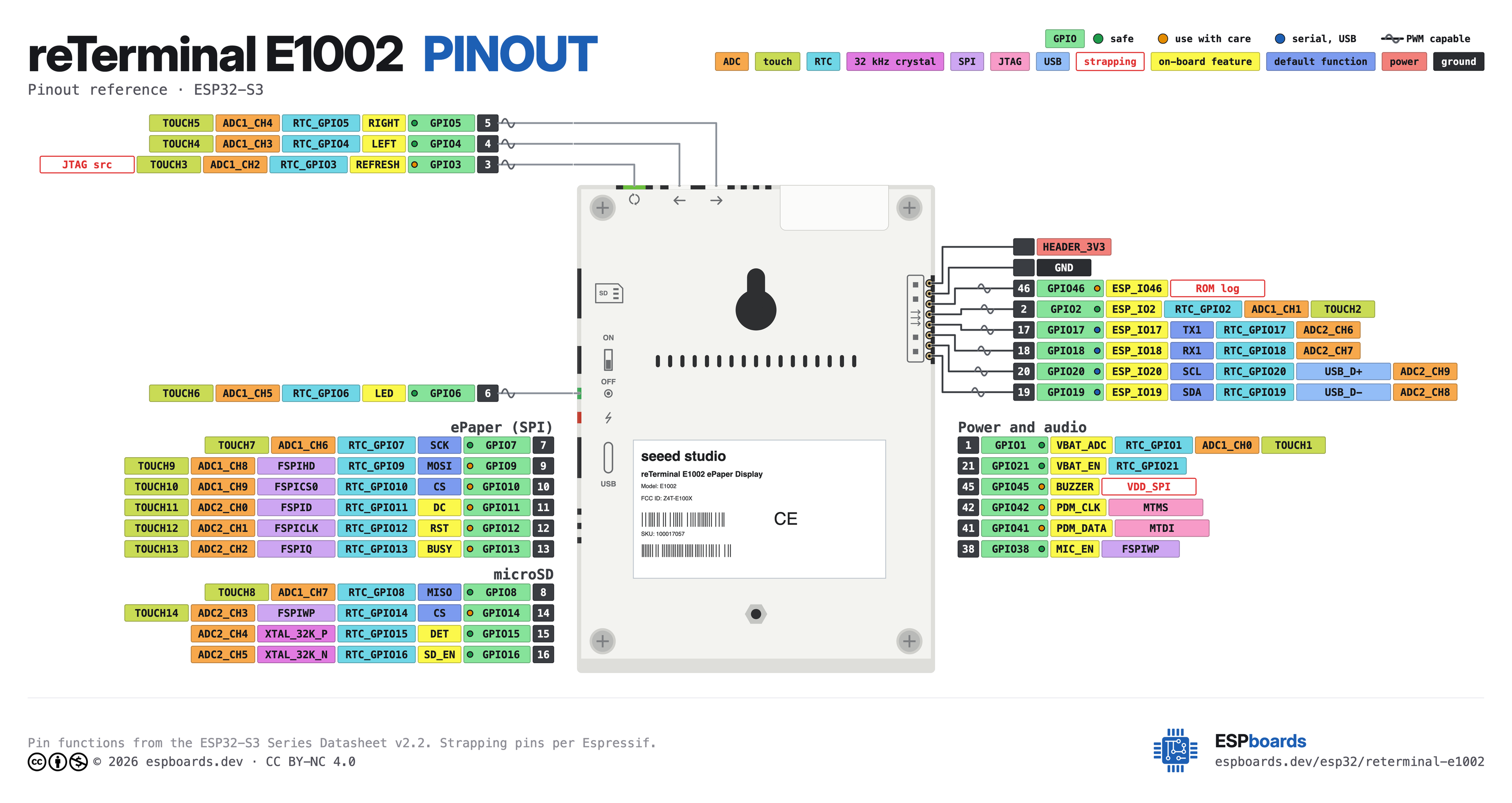
| Pin | GPIO | Labels | Status | Capabilities | Notes |
|---|---|---|---|---|---|
| 1 | - | HEADER_3V33V3 | power | - | 3.3V supply for the expansion header |
| 2 | - | GND | ground | - | Ground |
| 3 | 46 | ESP_IO46 | strapping | pwm | Strapping pin; no ADC despite the wiki label |
| 4 | 2 | ESP_IO2 | safe | adc · touch · pwm | ADC1_CH1 and TOUCH2 on the S3 (net name says ADC1_CH4) |
| 5 | 17 | ESP_IO17TX1 | uart | uart · adc · pwm | UART1 TX; ADC2_CH6, unusable while Wi-Fi is on |
| 6 | 18 | ESP_IO18RX1 | uart | uart · adc · pwm | UART1 RX; ADC2_CH7, unusable while Wi-Fi is on |
| 7 | 20 | ESP_IO20SCL | uart | i2c · adc · pwm | I2C0 SCL shared with the onboard SHT40 (0x44) and PCF8563 (0x51), 4.7k pull-ups; also the S3 USB D+ pad |
| 8 | 19 | ESP_IO19SDA | uart | i2c · adc · pwm | I2C0 SDA shared with the onboard SHT40 and PCF8563, 4.7k pull-ups; also the S3 USB D- pad |
Start with these
3 pins with no boot or system involvementFreely assignable - no strapping, flash, USB or JTAG duties. Ideal first picks for buttons, sensors and LEDs.
Fine - with a little care
1 pins · 1 thing to knowESP_IO46GPIO46 Bootstrapping pin (used with GPIO0 for boot mode; controls ROM log output) Strapping
Must be at a defined level during reset (with GPIO0) to select normal or download boot and UART/USB print mode. This pin is input-only (no output drive), so it should be left for its intended strapping function.
Only if you know the tricks
2 pins · 1 thing to knowESP_IO20GPIO20ESP_IO19GPIO19 USB OTG differential data pair (D- and D+) USB
By default connected to the on-chip USB Serial/JTAG controller. Using it as general GPIO without reconfiguring IO MUX will interfere with USB functionality.
- ESP_IO20USB OTG positive differential data line (USB_D+)
- ESP_IO19USB OTG negative differential data line (USB_D-)
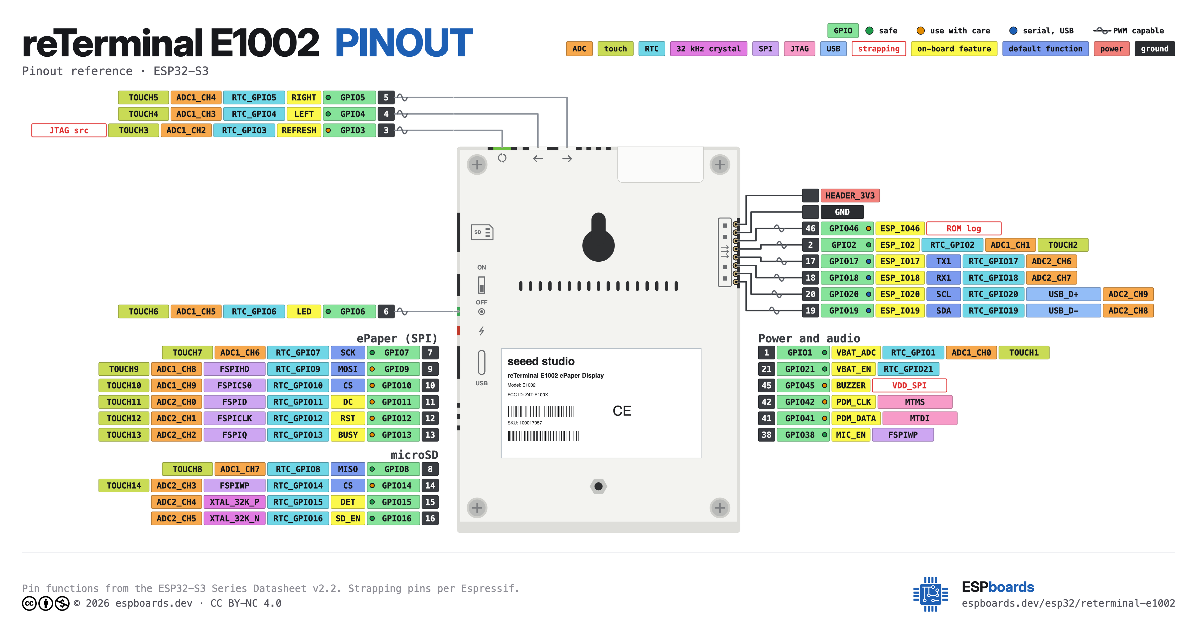
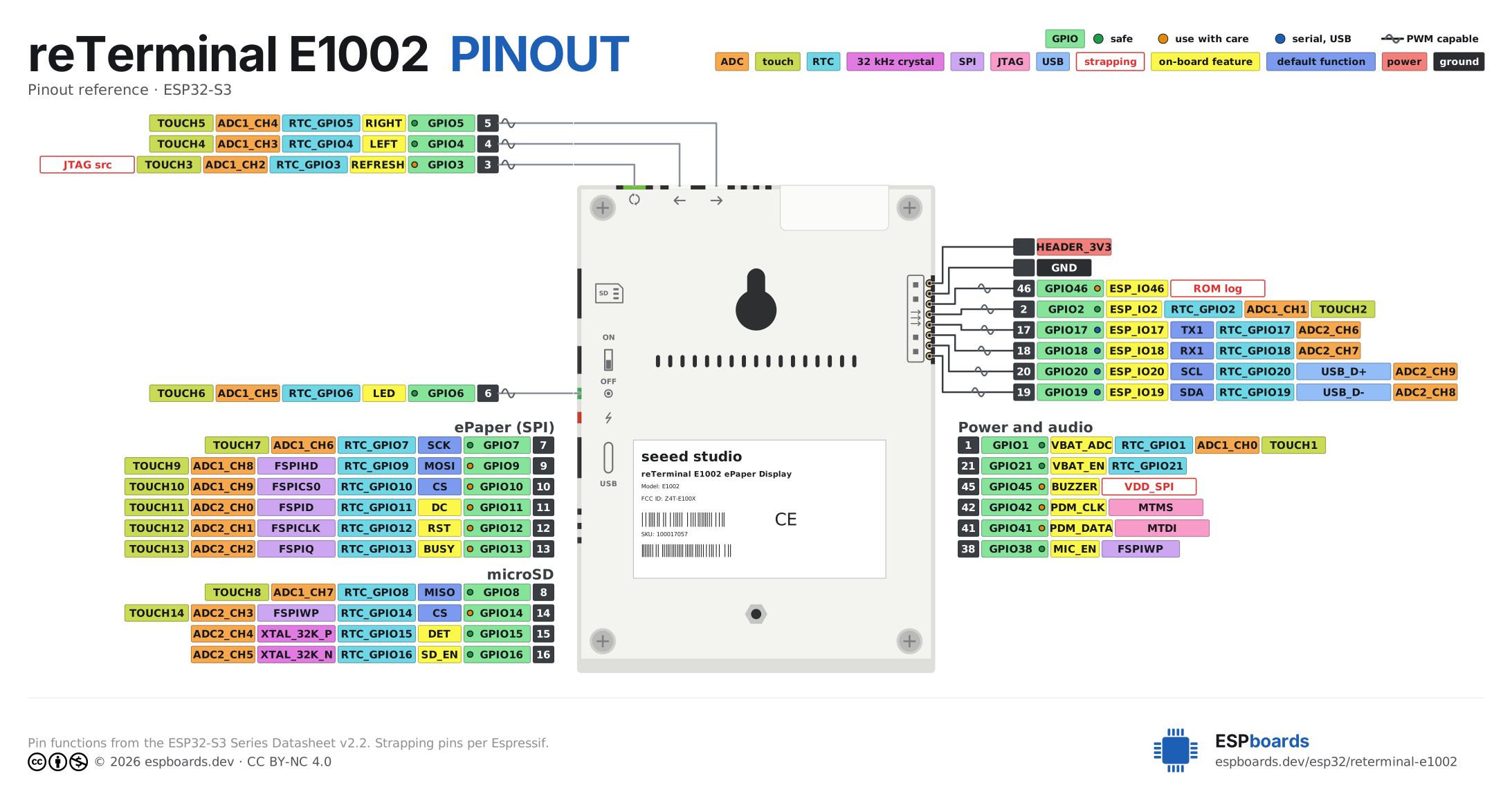
The reTerminal E1002 pinout brings out 8 pins - 6 usable GPIO alongside the HEADER_3V3 and GND power rails.
For peripherals, I²C is mapped to SDA on GPIO19 and SCL on GPIO20.
On the analog side there are 5 ADC-capable pins for sensors and battery monitoring, PWM on every GPIO and 1 capacitive-touch inputs.
If you want zero surprises, ESP_IO2, ESP_IO17 and ESP_IO18 are free of any such role - the safest first picks. 1 of the exposed pins carry boot-time or system duties on the ESP32-S3 (ESP_IO46).
Pinout notes Only eight pins leave the enclosure, on the J2 expansion header along the right edge with the device in landscape (USB-C and microSD on the left). There is no…
Only eight pins leave the enclosure, on the J2 expansion header along the right edge with the device in landscape (USB-C and microSD on the left). There is no per-pin silkscreen: pin 1 at the top is 3V3, then GND, GPIO46, GPIO2, GPIO17 (UART1 TX), GPIO18 (UART1 RX), GPIO20 (I2C0 SCL) and GPIO19 (I2C0 SDA). The I2C0 bus already carries the onboard SHT40 at 0x44 and the PCF8563 RTC at 0x51, with 4.7k pull-ups fitted, so add devices to it rather than repurposing the pins.
Check the header pins against the ESP32-S3 datasheet, not the wiki table. GPIO46 is a strapping pin with no ADC channel, despite being listed as GPIO/ADC; GPIO2 is ADC1_CH1 and TOUCH2 (the schematic net name says ADC1_CH4); and GPIO17/GPIO18 only have ADC2, which cannot be used while Wi-Fi is on. GPIO19/GPIO20 are the S3's native USB pads, which is why there is no USB CDC or USB-JTAG port: the USB-C connector goes through a CH340C to UART0 on GPIO43/GPIO44.
Everything else is internal. The ePaper hangs off SPI with GPIO7 SCK, GPIO9 MOSI, CS GPIO10, DC GPIO11, RST GPIO12 and BUSY GPIO13. The microSD shares SCK and MOSI, with chip select on GPIO14, card detect on GPIO15 and its 3.3V behind a TPS22916 load switch on GPIO16. Battery voltage reaches GPIO1 through a 10k/10k divider gated by GPIO21. The three top buttons are active-low on GPIO3 (green), GPIO4 and GPIO5, the green status LED is active-low on GPIO6, and an unpopulated touch-panel FPC connector sits on I2C1 (GPIO39 SDA, GPIO40 SCL, GPIO47 INT, GPIO48 RST).
Getting started
flash your first firmware in ~2 minutesBoard: XIAO_ESP32S3 Flash Size: 32MB (256Mb) Flash Mode: QIO PSRAM: OPI PSRAM Upload Speed: 921600
// blink the onboard user LED
void setup() {
  pinMode(6, OUTPUT);
}
void loop() {
  digitalWrite(6, HIGH); delay(500);
  digitalWrite(6, LOW);  delay(500);
}[env:reterminal-e1002]
platform = espressif32
board = seeed_xiao_esp32s3
framework = arduino
monitor_speed = 115200
upload_speed = 921600
board_build.arduino.memory_type = qio_opi
build_flags = -DBOARD_HAS_PSRAMseeed_xiao_esp32s3 - or type it after board =.esp32:
board: seeed_xiao_esp32s3
variant: esp32s3
framework:
type: esp-idf
psram:
mode: octal
speed: 80MHz
# blink - GPIO6
output:
- platform: gpio
pin: 6
id: led_out
light:
- platform: binary
name: "LED"
output: led_outseeed_xiao_esp32s3 (same ids as PlatformIO).esptool.py --chip esp32s3 --port /dev/ttyACM0 \
--baud 921600 write_flash 0x0 firmware.bin--port = your /dev/tty* (macOS/Linux) or COMx (Windows).Good to know
board-specific quirks worth 60 secondsNo native USB, and the recommended board profile assumes there is one. The USB-C port goes to a CH340C USB-UART bridge on UART0 (GPIO43/GPIO44). The ESP32-S3's own USB pads, GPIO19 and GPIO20, are used as the I2C0 pins on the expansion header instead, so there is no USB CDC or USB-JTAG port on this device. Serial output has to go through the CH340C. The XIAO_ESP32S3 profile Seeed tells you to select…
No native USB, and the recommended board profile assumes there is one. The USB-C port goes to a CH340C USB-UART bridge on UART0 (GPIO43/GPIO44). The ESP32-S3's own USB pads, GPIO19 and GPIO20, are used as the I2C0 pins on the expansion header instead, so there is no USB CDC or USB-JTAG port on this device. Serial output has to go through the CH340C.
The XIAO_ESP32S3 profile Seeed tells you to select enables USB CDC On Boot, which points Serial at USB pins that are not wired to USB. Print through Serial0 (the UART0 port behind the CH340C), or set USB CDC On Boot to Disabled in the Tools menu.
The Boot and Reset switches sit inside the sealed enclosure. Flashing relies on the CH340C DTR/RTS auto-reset circuit, so no boot-mode button press is needed from outside.
Every update is a 15-20 s full refresh. Spectra 6 has no partial refresh, where the monochrome E1001 sibling manages partial updates in 2-5 s. Plan a low update rate: one review measured about 18 days of battery at a 30-minute refresh interval, roughly half the E1001 under the same schedule. Do not enter deep sleep straight after starting a refresh. Cutting the color cycle short leaves wrong colors or a…
Every update is a 15-20 s full refresh. Spectra 6 has no partial refresh, where the monochrome E1001 sibling manages partial updates in 2-5 s. Plan a low update rate: one review measured about 18 days of battery at a 30-minute refresh interval, roughly half the E1001 under the same schedule.
Do not enter deep sleep straight after starting a refresh. Cutting the color cycle short leaves wrong colors or a partial image; one Home Assistant user adds about 15 s of margin before sleeping.
Downloads
Free for non-commercial use, credit espboards.dev · License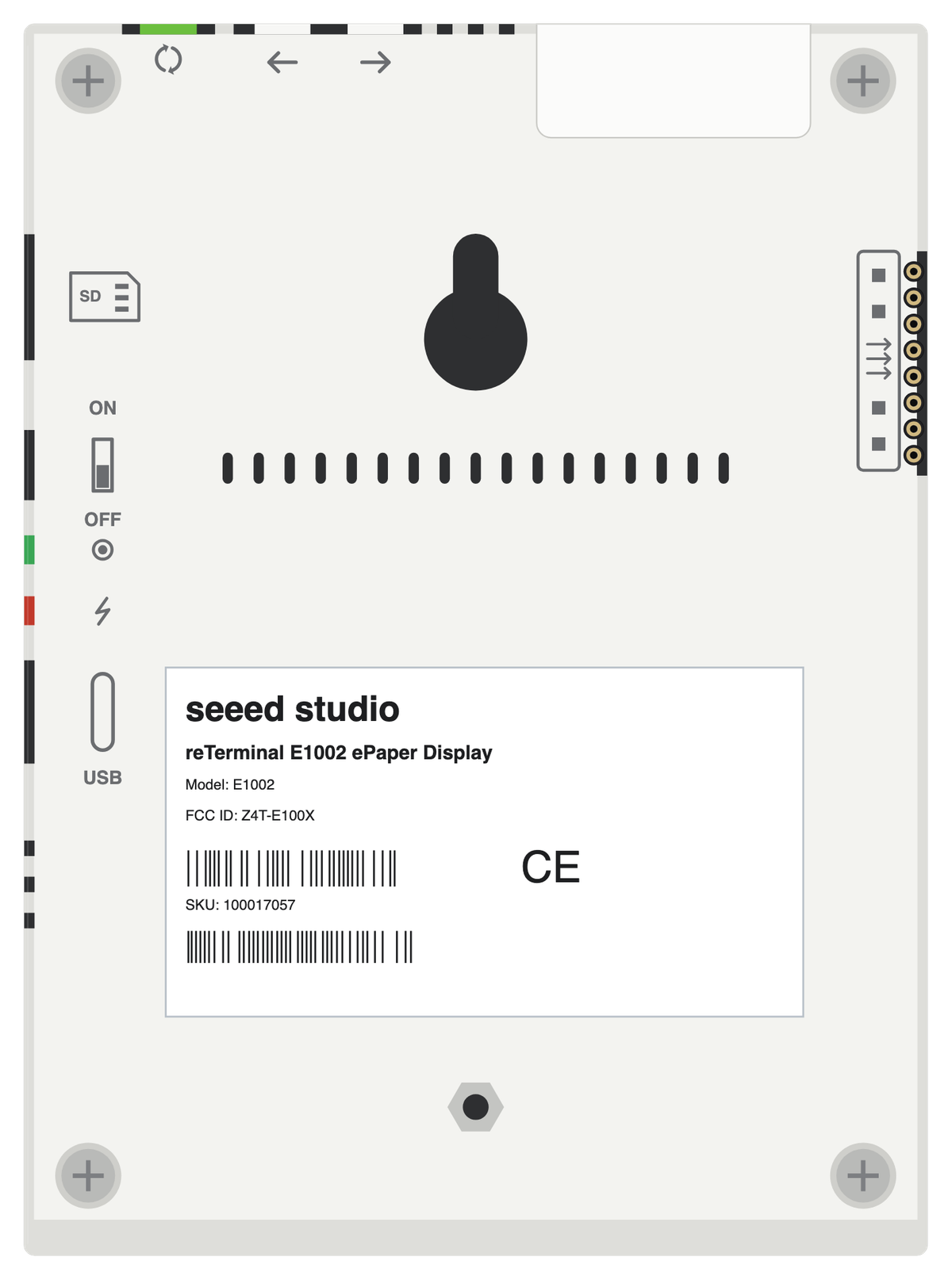
Board illustration
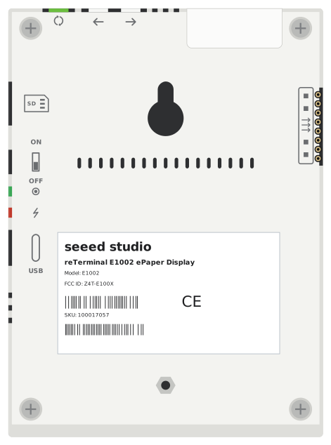
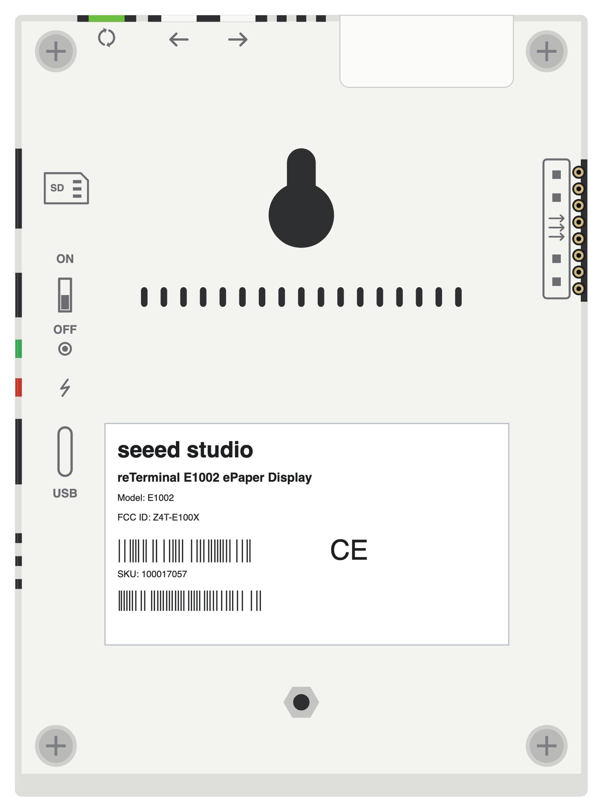
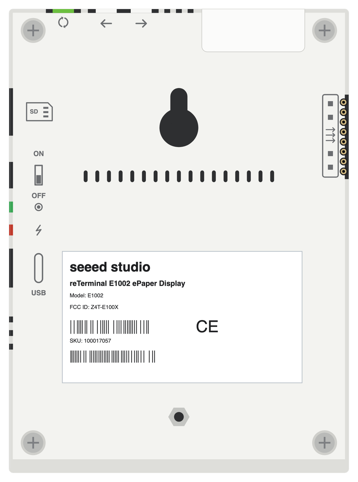
The bare reTerminal E1002 board drawn to scale at 120.2 × 175.2 mm, with no pin labels on it. Made for slide decks, wiring diagrams and project write-ups where a photo is too busy. Take the scalable SVG for print or editing, the high-resolution PNG to drop straight in, or the transparent PNG when you need it with no background behind it.
Pinout diagram
Every pin on both sides of the board with its functions, drawn by ESPboards from the ESP32-S3 Series Datasheet v2.2 - the same sheet shown at the top of this page. The PNG is a high-resolution image for screens, the SVG is vector so it stays sharp at any size, and the PDF is laid out to print on A4 or Letter.
Yours to use, share and adapt for non-commercial work, as long as you credit espboards.dev - the full terms and ready-made credit lines are here.
Specifications
ESP32-S3 · 120.2 × 175.2 mm · vs other ESP32 chips →Dimensions
About this board
At its core is the ESP32-S3 - a dual-core Xtensa with vector extensions suited to AI workloads.
Expect to pay about $109.00 - above the ~$29 typical for ESP32-S3 boards.
Only 6 GPIO are left for your own hardware - the display and onboard peripherals claim the rest.
Onboard you'll find 8MB (OPI) PSRAM, an ePaper 7.3" 800x480 display, a microSD slot, a microphone (PDM MEMS), a PCF8563 RTC, a buzzer, an environmental sensor (SHT40), battery charging (SY6974B) via JST-PH 2.0 (internal, 2000mAh cell fitted), status LEDs (Green status (GPIO6 active-low), Red charge) and Reset/Boot/3 user (GPIO3 green / GPIO4 / GPIO5) buttons.
The reTerminal E1002 is Seeed Studio's 7.3 inch color ePaper dashboard: an E Ink Spectra 6 panel (800x480, six colors - black, white, red, yellow, green and blue) in a metal enclosure with a detachable stand, driven by an ESP32-S3R8 with 32 MB flash and 8 MB octal PSRAM. Inside are a 2000 mAh Li-Po that Seeed rates at about three months per charge, a microSD slot, an SHT40 temperature and humidity sensor, a PCF8563 RTC with an empty CR1220 holder, a PDM microphone, a buzzer and three user buttons. The only external I/O is an 8-pin header carrying I2C, UART1 and two spare GPIOs.
It is sold as a finished device rather than a bare board. Seeed's browser-based firmware hub flashes SenseCraft HMI, ESPHome, TRMNL, LVGL and EEZ Studio builds over USB serial, and there is a documented ESPHome route for Home Assistant dashboards. Arduino and PlatformIO work too, through the XIAO_ESP32S3 profile with OPI PSRAM and Seeed's GFX driver, with one wrinkle: the USB-C port is a CH340C UART bridge rather than native USB, so the profile's USB CDC On Boot setting has to be switched off or Serial0 used instead.
The trade-off is the panel. Spectra 6 has no partial refresh, so every update is a 15-20 s full redraw, and the color model runs about half as long per charge as its monochrome sibling, the reTerminal E1001, which manages partial updates in 2-5 s. One review measured about 18 days at a 30-minute refresh interval. It suits a wall or desk dashboard that updates a few times an hour and gets charged over USB-C now and then, not anything that needs a responsive screen.
- Built-in 3.7V 2000mAh Li-Po (7.4Wh), rated for about 3 months per charge
- Deep sleep around 14uA
- E Ink Spectra 6 panel: black, white, red, yellow, green, blue; full refresh 15-20 s, no partial refresh
- Metal enclosure with detachable stand, 176 x 120 x 53 mm on the stand, 17 mm thick without it
- Browser-based firmware hub flashes SenseCraft HMI, ESPHome, TRMNL, LVGL and EEZ Studio builds over USB serial
- Unpopulated 24-pin touch-panel FPC connector on I2C1 (GPIO39 SDA, GPIO40 SCL, GPIO47 INT, GPIO48 RST)
- CR1220 holder for the RTC backup cell, shipped empty
FAQ
6 common questionsDoes the reTerminal E1002 work with ESPHome?›
How do I program the reTerminal E1002 in Arduino IDE or PlatformIO?›
How do I read the battery voltage?›
How do I use the microSD slot?›
What is the difference between the reTerminal E1001 and E1002?›
Where are the buttons, and which LED can I control?›
Where to buy
prices are typical street pricesResources
Similar boards

