
LilyGO T7-C6
Feature-rich ESP32-C6 board with extended I/O and USB-C - great for prototyping connected devices with Matter support.

LilyGO T7-C6 Pinout
25 pins · 2.54 mm pitch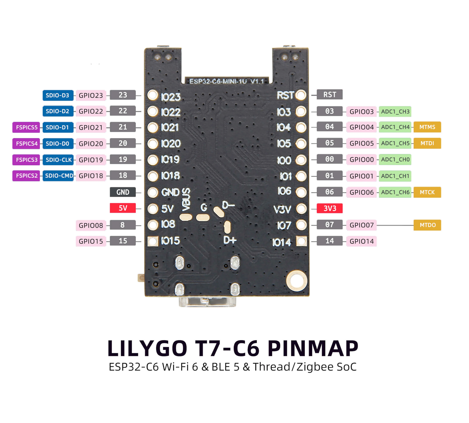
| Pin | GPIO | Labels | Status | Capabilities | Notes |
|---|---|---|---|---|---|
| 1 | 23 | IO23SDIO-D3 | safe | - | Left header. GPIO; SDIO data 3. |
| 2 | 22 | IO22SDIO-D2 | safe | - | Left header. GPIO; SDIO data 2. |
| 3 | 21 | IO21SDIO-D1 | safe | - | Left header. GPIO; SDIO data 1, FSPI chip select. |
| 4 | 20 | IO20SDIO-D0 | safe | - | Left header. GPIO; SDIO data 0, FSPI chip select. |
| 5 | 19 | IO19SDIO-CLK | safe | - | Left header. GPIO; SDIO clock, FSPI chip select. |
| 6 | 18 | IO18SDIO-CMD | safe | - | Left header. GPIO; SDIO command, FSPI chip select. |
| 7 | - | GND | ground | - | Left header. Ground. |
| 8 | - | 5V | power | - | Left header. 5V input/output (USB VBUS). |
| 9 | 8 | IO8 | strapping | - | Left header. GPIO; strapping pin (boot mode). |
| 10 | 15 | IO15 | strapping | - | Left header. GPIO; strapping pin. |
| 11 | - | RST | control | - | Right header. Chip reset (active low). |
| 12 | 3 | IO3 | safe | adc | Right header. GPIO; ADC1 channel 3. |
| 13 | 4 | IO4MTMS | strapping | adc | Right header. GPIO; ADC1 channel 4, JTAG MTMS. |
| 14 | 5 | IO5MTDI | strapping | adc | Right header. GPIO; ADC1 channel 5, JTAG MTDI. |
| 15 | 0 | IO0 | safe | adc | Right header. GPIO; ADC1 channel 0. |
| 16 | 1 | IO1 | safe | adc | Right header. GPIO; ADC1 channel 1. |
| 17 | 6 | IO6MTCK | strapping | adc | Right header. GPIO; ADC1 channel 6, JTAG MTCK. |
| 18 | - | 3V33.3V | power | - | Right header. 3.3V regulated output. |
| 19 | 7 | IO7MTDO | strapping | - | Right header. GPIO; JTAG MTDO. |
| 20 | 14 | IO14 | safe | - | Right header. GPIO. |
| 21 | - | VBUS | power | - | Center USB pad. USB-C VBUS (5V). |
| 22 | - | G | ground | - | Center USB pad. Ground. |
| 23 | 12 | D- | usb | - | Center USB pad. USB-C D- data line (native USB). |
| 24 | 13 | D+ | usb | - | Center USB pad. USB-C D+ data line (native USB). |
| 25 | 2 | IO2 | safe | adc | Onboard battery voltage divider (reads LiPo voltage / 2); not broken out to a header. |
Start with these
11 pins with no boot or system involvementFreely assignable - no strapping, flash, USB or JTAG duties. Ideal first picks for buttons, sensors and LEDs.
Fine - with a little care
6 pins · 5 things to knowIO8 Boot mode strapping pin; also gates ROM boot message printing (UART_PRINT_CONTROL efuse). Strapping
Determines boot mode; pulling low at reset can prevent normal boot.
IO15 JTAG source selection pin. JTAG
Controls JTAG input source at boot; avoid altering its state.
IO4IO5 Bootstrapping pins; JTAG TMS and TDI; flash data lines on internal-flash models Strapping
Used during boot; required for JTAG debugging; flash data in internal-flash models.
- IO4Bootstrapping pin; JTAG TMS; Flash data (FSPIHD in internal-flash models).
- IO5Bootstrapping pin; JTAG TDI; Flash data (FSPIWP in internal-flash models).
IO6 JTAG TCK; Used for flash clock (internal-flash models). JTAG
Required for JTAG debugging; connected to flash clock in internal-flash models.
IO7 JTAG TDO; Used for flash data (FSPI DO in internal-flash models). JTAG
Required for JTAG debugging; connected to flash data in internal-flash models.
Only if you know the tricks
2 pins · 1 thing to knowD-GPIO12D+GPIO13 USB differential data pair (D- and D+) USB
Dedicated to USB communication; avoid if using USB functionality.
- D-USB D- (USB communication).
- D+USB D+ (USB communication).
The LilyGO T7-C6 pinout brings out 25 pins at a 2.54 mm pitch - 17 usable GPIO alongside the GND, 5V, 3V3, VBUS and G power rails.
Beyond plain digital I/O you get 7 ADC-capable pins for sensors and battery monitoring.
6 of the exposed pins carry boot-time or system duties on the ESP32-C6 (IO8, IO15, IO4 and 3 more) - check the guidance above before wiring anything to them. IO23, IO22, IO21, IO20 and 7 more are free of any such role - the safest first picks.
Getting started
flash your first firmware in ~2 minutesBoard: ESP32C6 Dev Module USB CDC On Boot: Enabled Flash Size: 4MB (32Mb) Flash Mode: QIO Partition Scheme: Default 4MB with spiffs (1.2MB APP/1.5MB SPIFFS) Upload Speed: 921600
// toggle GPIO23 - wire an LED and resistor to it
void setup() {
  pinMode(23, OUTPUT);
}
void loop() {
  digitalWrite(23, HIGH); delay(500);
  digitalWrite(23, LOW);  delay(500);
}[env:t7-c6]
platform = https://github.com/pioarduino/platform-espressif32/releases/download/stable/platform-espressif32.zip
board = esp32-c6-devkitc-1
framework = arduino
monitor_speed = 115200
upload_speed = 921600esp32-c6-devkitc-1 - or type it after board =.esp32:
board: esp32-c6-devkitc-1
variant: esp32c6
framework:
type: esp-idf
# blink - GPIO23
output:
- platform: gpio
pin: 23
id: led_out
light:
- platform: binary
name: "LED"
output: led_outesp32-c6-devkitc-1 (same ids as PlatformIO).esptool.py --chip esp32c6 --port /dev/ttyACM0 \
--baud 921600 write_flash 0x0 firmware.bin--port = your /dev/tty* (macOS/Linux) or COMx (Windows).Good to know
board-specific quirks worth 60 seconds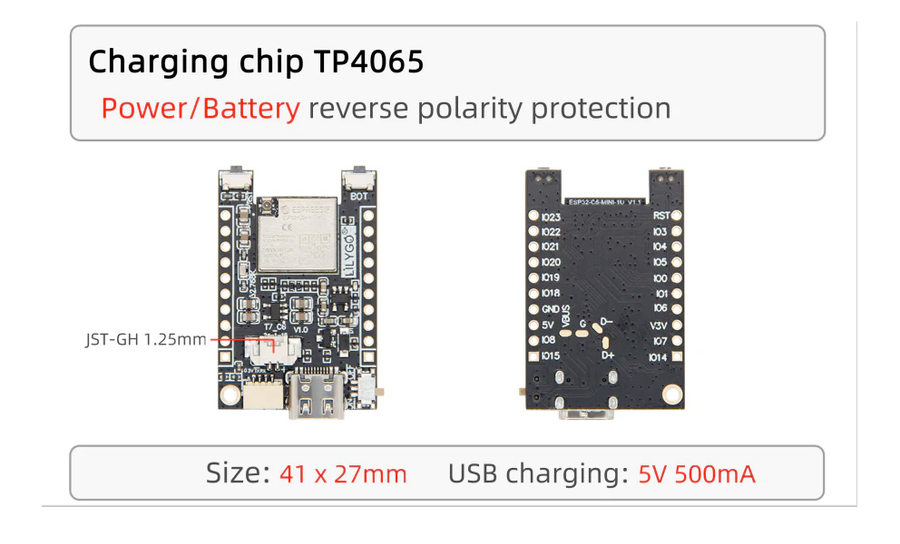
Specifications
ESP32-C6 · 41 × 27 mm · vs other ESP32 chips →Dimensions
About this board
Inside sits the ESP32-C6 - a RISC-V part adding Wi-Fi 6 plus Thread/Zigbee radios.
At $15.00 it's on the expensive side for an ESP32-C6 board - most land around $10.
Only 17 GPIO are broken out, where most ESP32-C6 boards manage about 22 - worth checking the pinout covers what you need.
Around the module: a Qwiic connector, battery charging (TP4065) via JST-GH 1.25 and Boot/Reset buttons.
It flashes over native USB - no serial-converter driver needed, which isn't a given among ESP32-C6 boards.
- RISC-V ESP32-C6 processor with ultra-low power consumption
- Supports WiFi 6, Bluetooth 5 (LE), and Zigbee
- Compact design ideal for IoT and sensor applications
- USB-C for programming and power
Where to buy
prices are typical street pricesResources
Similar boards


