
ESP32-C6 Super Mini
Tiny ESP32-C6 board with Wi-Fi 6, BLE 5.3, and Thread - perfect for future-proof, low-power IoT and Matter-enabled projects.

ESP32-C6 Super Mini Pinout
26 pins · 2.54 mm pitch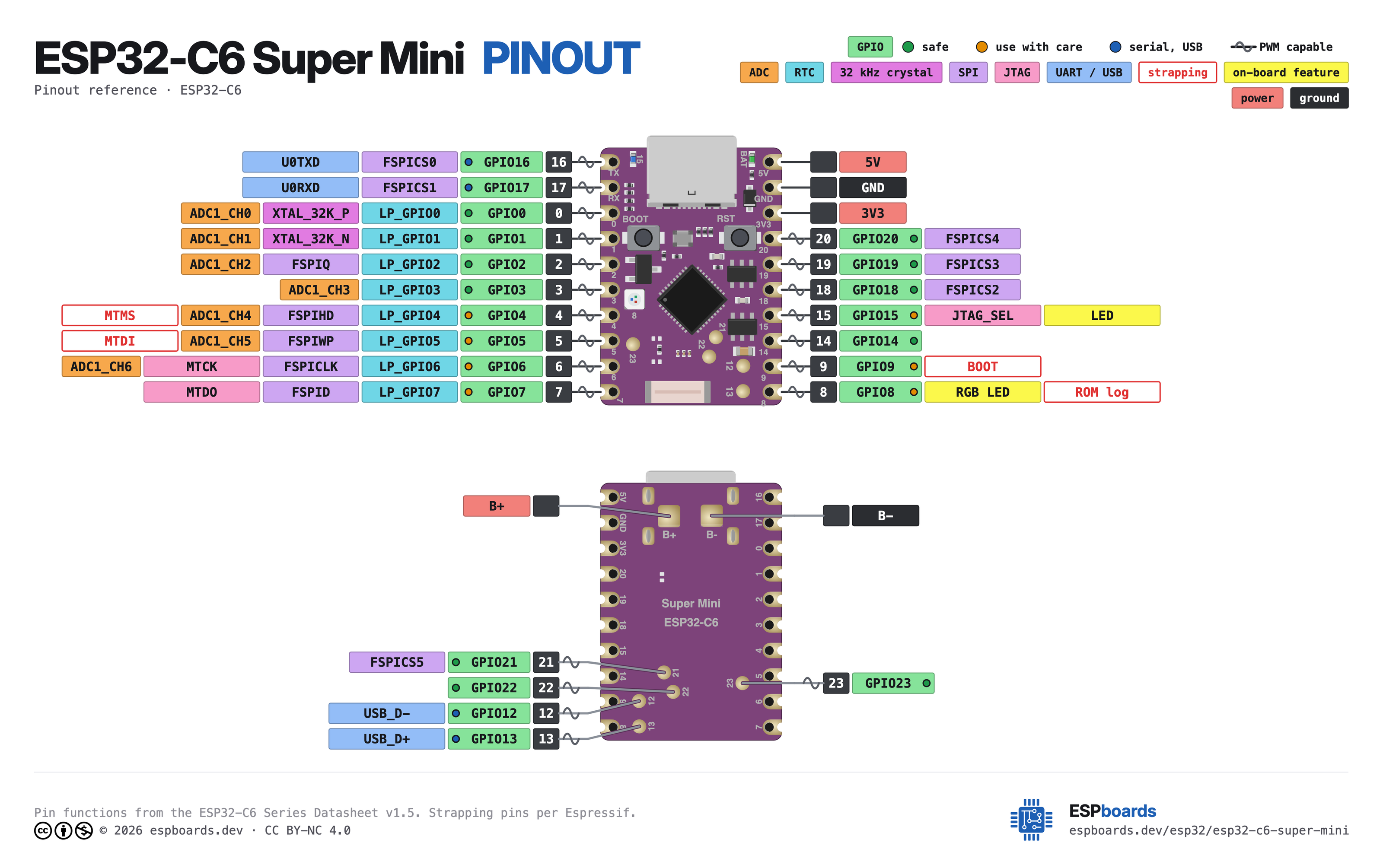
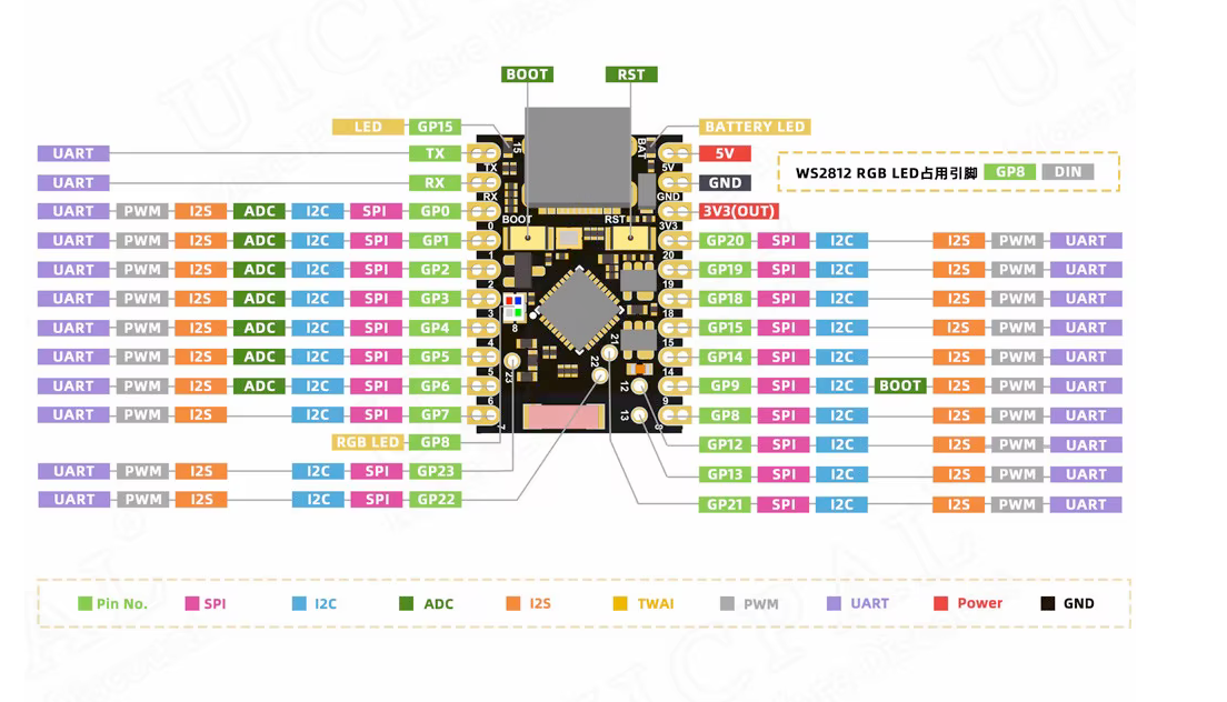
| Pin | GPIO | Labels | Status | Capabilities | Notes |
|---|---|---|---|---|---|
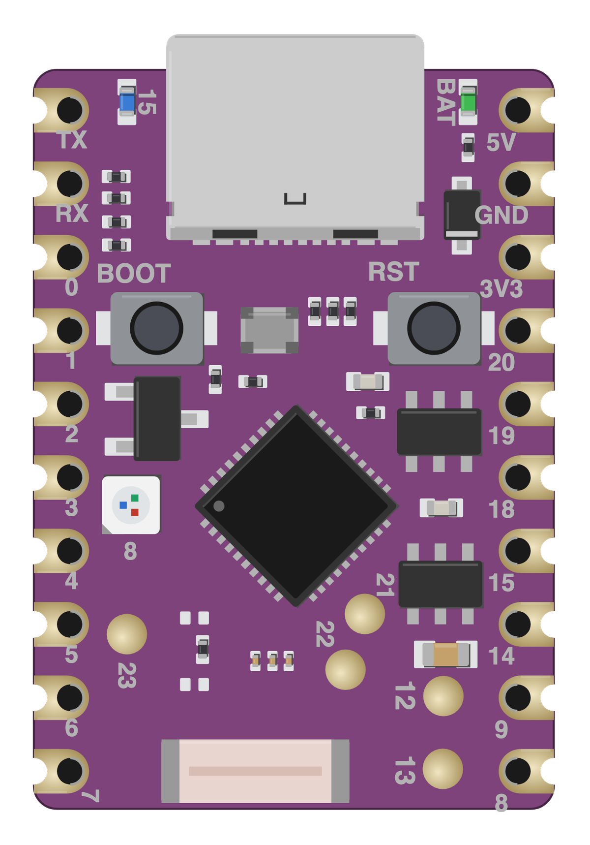
| 1 | - | BAT | power | - | Lithium battery input for the onboard charger. NOT a header pin - it is a separate pad beside the USB connector, with BAT printed turned beside it. The right header's ten pads are 5V GND 3V3 20 19 18 15 14 9 8, each with its name printed just past it toward the antenna end, the same way the left row prints TX RX 0-7. |
| 2 | - | 5V | power | - | 5V power input for the board |
| 3 | - | GND | ground | - | Ground connection |
| 4 | - | 3V33.3V | power | - | 3.3V power output for peripherals |
| 5 | 16 | TXIO16 | uart | uart | TX |
| 6 | 17 | RXIO17 | uart | uart | RX |
| 7 | 0 | IO0GP0 | safe | adc | GPIO, ADC pin |
| 8 | 1 | IO1GP1 | safe | adc | GPIO, ADC pin |
| 9 | 2 | IO2GP2 | safe | adc | GPIO, ADC pin |
| 10 | 3 | IO3GP3 | safe | adc | GPIO, ADC pin |
| 11 | 4 | IO4GP4 | strapping | adc | GPIO, ADC pin |
| 12 | 5 | IO5GP5 | strapping | adc | GPIO, ADC pin |
| 13 | 6 | IO6GP6 | strapping | adc | GPIO, ADC pin |
| 14 | 7 | IO7GP7 | strapping | - | GPIO |
| 15 | 8 | IO8GP8 | strapping | - | GPIO, RGB LED |
| 16 | 9 | IO9GP9 | strapping | - | GPIO, Boot |
| 17 | 12 | IO12GP12 | uart | - | GPIO |
| 18 | 13 | IO13GP13 | uart | - | GPIO |
| 19 | 14 | IO14GP14 | safe | - | GPIO |
| 20 | 15 | IO15GP15 | strapping | - | GPIO, LED |
| 21 | 18 | IO18GP18 | safe | - | GPIO |
| 22 | 19 | IO19GP19 | safe | - | GPIO |
| 23 | 20 | IO20GP20 | safe | - | GPIO |
| 24 | 21 | IO21GP21 | safe | - | GPIO |
| 25 | 22 | IO22GP22 | safe | - | GPIO |
| 26 | 23 | IO23GP23 | safe | - | GPIO |
Start with these
11 pins with no boot or system involvementFreely assignable - no strapping, flash, USB or JTAG duties. Ideal first picks for buttons, sensors and LEDs.
Fine - with a little care
9 pins · 8 things to knowTXGPIO16 UART0 TX; Flash CS0 (internal-flash models). UART
Default UART0 transmit pin; using it may interfere with serial console or programming.
RXGPIO17 UART0 RX. UART
Default UART0 receive pin; using it may interfere with serial console or programming.
IO4IO5 Bootstrapping pins; JTAG TMS and TDI; flash data lines on internal-flash models Strapping
Used during boot; required for JTAG debugging; flash data in internal-flash models.
- IO4Bootstrapping pin; JTAG TMS; Flash data (FSPIHD in internal-flash models).
- IO5Bootstrapping pin; JTAG TDI; Flash data (FSPIWP in internal-flash models).
IO6 JTAG TCK; Used for flash clock (internal-flash models). JTAG
Required for JTAG debugging; connected to flash clock in internal-flash models.
IO7 JTAG TDO; Used for flash data (FSPI DO in internal-flash models). JTAG
Required for JTAG debugging; connected to flash data in internal-flash models.
IO8 Boot mode strapping pin; also gates ROM boot message printing (UART_PRINT_CONTROL efuse). Strapping
Determines boot mode; pulling low at reset can prevent normal boot.
IO9 Boot mode strapping pin. Strapping
Pulling low on reset forces the ESP32-C6 into download mode instead of normal boot.
IO15 JTAG source selection pin. JTAG
Controls JTAG input source at boot; avoid altering its state.
Only if you know the tricks
2 pins · 1 thing to knowIO12IO13 USB differential data pair (D- and D+) USB
Dedicated to USB communication; avoid if using USB functionality.
- IO12USB D- (USB communication).
- IO13USB D+ (USB communication).
Across 26 pins (2.54 mm pitch), the ESP32-C6 Super Mini exposes 22 GPIO plus BAT, 5V, GND and 3V3 for power.
Peripheral wiring is straightforward: TX/RX on GPIO16 and GPIO17 cover serial logging and flashing.
Beyond plain digital I/O you get 7 ADC-capable pins for sensors and battery monitoring.
9 of the exposed pins carry boot-time or system duties on the ESP32-C6 (TX, RX, IO4 and 6 more) - check the guidance above before wiring anything to them. IO0, IO1, IO2, IO3 and 7 more are free of any such role - the safest first picks.
Pinout notes The ESP32-C6 Super Mini pinout is designed for versatile connectivity in a compact format. The board provides essential power pins such as 5V, 3.3V, and GND…
The ESP32-C6 Super Mini pinout is designed for versatile connectivity in a compact format. The board provides essential power pins such as 5V, 3.3V, and GND for stable power delivery.
It features dedicated communication interfaces including RX and TX for UART, SDA and SCL for I2C, and MISO, MOSI, SCK, and SS for SPI, ensuring seamless integration with peripherals.
For analog input, the ESP32-C6 Super Mini offers ADC pins labeled A0 to A5, supporting sensor applications. Additionally, it features a stamp hole design for direct soldering, providing improved reliability for embedded applications.
Guides & tutorials

Getting started
flash your first firmware in ~2 minutesBoard: ESP32C6 Dev Module USB CDC On Boot: Enabled Flash Size: 4MB (32Mb) Flash Mode: QIO Partition Scheme: Default 4MB with spiffs (1.2MB APP/1.5MB SPIFFS) Upload Speed: 921600
// toggle GPIO0 - wire an LED and resistor to it
void setup() {
  pinMode(0, OUTPUT);
}
void loop() {
  digitalWrite(0, HIGH); delay(500);
  digitalWrite(0, LOW);  delay(500);
}[env:esp32-c6-super-mini]
platform = https://github.com/pioarduino/platform-espressif32/releases/download/stable/platform-espressif32.zip
board = esp32-c6-devkitc-1
framework = arduino
monitor_speed = 115200
upload_speed = 921600esp32-c6-devkitc-1 - or type it after board =.esp32:
board: esp32-c6-devkitc-1
variant: esp32c6
framework:
type: esp-idf
# blink - GPIO0
output:
- platform: gpio
pin: 0
id: led_out
light:
- platform: binary
name: "LED"
output: led_outesp32-c6-devkitc-1 (same ids as PlatformIO).esptool.py --chip esp32c6 --port /dev/ttyACM0 \
--baud 921600 write_flash 0x0 firmware.bin--port = your /dev/tty* (macOS/Linux) or COMx (Windows).Good to know
board-specific quirks worth 60 seconds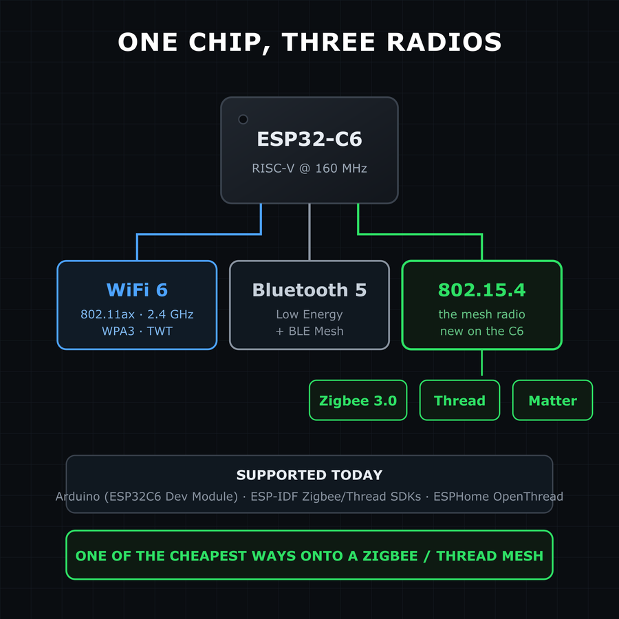
What separates the C6 from every other SuperMini is its third radio: alongside WiFi 6 and Bluetooth 5 LE, the ESP32-C6 has an IEEE 802.15.4 radio - the one Zigbee and Thread run on. That makes this ~$5 board one of the cheapest ways to build a Zigbee 3.0 device, a Thread node, or a Matter-over-Thread endpoint. Tooling has caught up: Arduino supports the C6 via the standard ESP32 core (ESP32C6 Dev Module), ESP-IDF…
What separates the C6 from every other SuperMini is its third radio: alongside WiFi 6 and Bluetooth 5 LE, the ESP32-C6 has an IEEE 802.15.4 radio - the one Zigbee and Thread run on. That makes this ~$5 board one of the cheapest ways to build a Zigbee 3.0 device, a Thread node, or a Matter-over-Thread endpoint.
Tooling has caught up: Arduino supports the C6 via the standard ESP32 core (ESP32C6 Dev Module), ESP-IDF has full Zigbee/Thread SDKs, and ESPHome ships OpenThread support since 2025.6.
If your smart home is drowning in 2.4 GHz WiFi devices, this board lets the sensor live on the Zigbee/Thread mesh instead - same price, quieter airwaves.
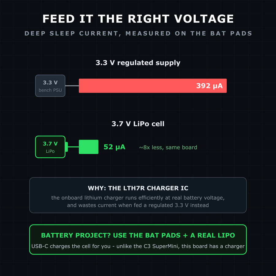
Unlike the C3 SuperMini, this board has battery pads with a real charging circuit (an LTH7R linear charger) - plug in a LiPo and USB-C tops it up. And its sleep numbers are in a different league from classic dev boards: measurements on this exact board show deep sleep in the tens of microamps. The quirk: those measurements found the sleep current depends heavily on what voltage you feed the BAT pin - about 392 µA at…
Unlike the C3 SuperMini, this board has battery pads with a real charging circuit (an LTH7R linear charger) - plug in a LiPo and USB-C tops it up. And its sleep numbers are in a different league from classic dev boards: measurements on this exact board show deep sleep in the tens of microamps.
The quirk: those measurements found the sleep current depends heavily on what voltage you feed the BAT pin - about 392 µA at 3.3 V, dropping to roughly 52 µA at 3.7 V. The charger IC simply runs more efficiently at real lithium-cell voltages.
For battery projects, power it from an actual 3.7 V LiPo on the BAT pads - not a regulated 3.3 V bench supply - and you get nearly 8x the sleep efficiency for free.
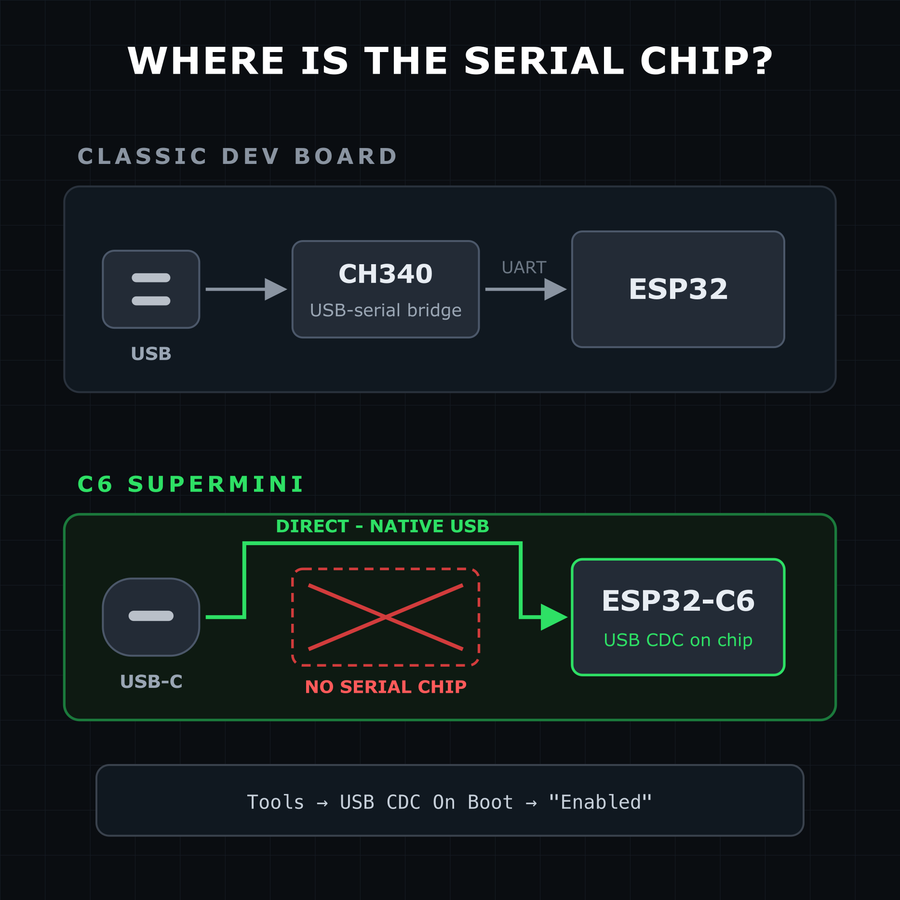
Like the other SuperMinis, the C6 has no USB-to-serial converter chip - the USB-C port connects straight to the ESP32-C6's native USB. Two everyday consequences: Serial output: enable Tools → USB CDC On Boot → "Enabled" in Arduino IDE, or Serial.print() goes to the UART pins instead of your serial monitor. Flashing: if the COM port never appears or an upload fails, hold BOOT while plugging in USB (or while tapping…
Like the other SuperMinis, the C6 has no USB-to-serial converter chip - the USB-C port connects straight to the ESP32-C6's native USB. Two everyday consequences:
- Serial output: enable Tools → USB CDC On Boot → "Enabled" in Arduino IDE, or
Serial.print()goes to the UART pins instead of your serial monitor. - Flashing: if the COM port never appears or an upload fails, hold BOOT while plugging in USB (or while tapping RESET) to force the ROM bootloader, then press RESET after flashing.
A crashed or deep-sleeping sketch takes the USB port down with it - normal for native-USB boards, not a broken board. The BOOT-button trick always recovers it.
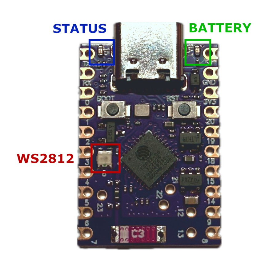
The ESP32-C6 Supermini features three onboard LEDs: a green battery indicator, a user-controllable status LED, and a WS2812 RGB LED. The WS2812 is connected to GPIO8, while the simple status LED is on GPIO15. Green LED - Battery Charge Indicator GPIO: None Control: Not controllable via GPIO Behavior: Charging → LED on Battery connected → LED off No battery → LED blinks Status LED - User Controllable GPIO: GPIO15…
The ESP32-C6 Supermini features three onboard LEDs: a green battery indicator, a user-controllable status LED, and a WS2812 RGB LED. The WS2812 is connected to GPIO8, while the simple status LED is on GPIO15.
Green LED - Battery Charge Indicator
- GPIO:
None - Control: Not controllable via GPIO
- Behavior:
- Charging → LED on
- Battery connected → LED off
- No battery → LED blinks
Status LED - User Controllable
- GPIO:
GPIO15 - Control:
digitalWrite(), ESPHome GPIO output
void setup() {
  pinMode(15, OUTPUT);
}

void loop() {
  digitalWrite(15, HIGH);
  delay(1000);
  digitalWrite(15, LOW);
  delay(1000);
}
output:
  - platform: gpio
    pin: 15
    id: status_led

light:
  - platform: binary
    name: "Status LED"
    output: status_led
WS2812 LED - Programmable RGB
- GPIO:
GPIO8 - Control: FastLED, NeoPixel, etc.
#include <FastLED.h>

#define NUM_LEDS 1
#define DATA_PIN 8

CRGB leds[NUM_LEDS];

void setup() {
  FastLED.addLeds<NEOPIXEL, DATA_PIN>(leds, NUM_LEDS);
}

void loop() {
  leds[0] = CRGB::Red; FastLED.show(); delay(1000);
  leds[0] = CRGB::Green; FastLED.show(); delay(1000);
  leds[0] = CRGB::Blue; FastLED.show(); delay(1000);
light:
  - platform: esp32_rmt_led_strip
    chipset: WS2812
    pin: GPIO8
    num_leds: 1
    rgb_order: GRB
name: "Onboard RGB LED"Downloads
Free for non-commercial use, credit espboards.dev · License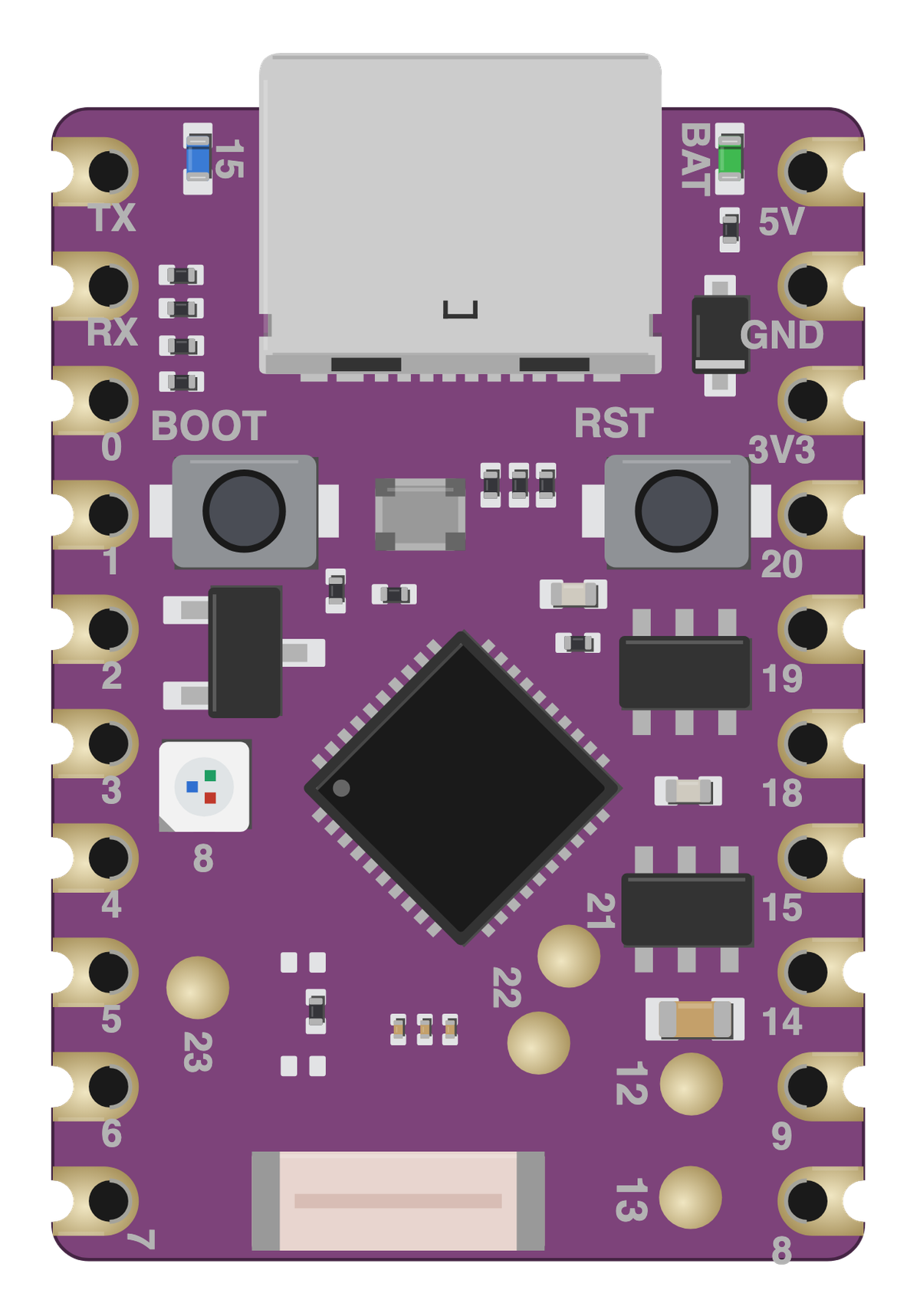
Board illustration
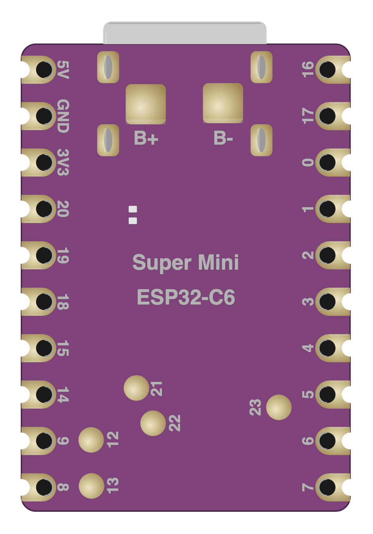
The bare ESP32-C6 Super Mini board drawn to scale at 25.56 × 18 mm, with no pin labels on it. Made for slide decks, wiring diagrams and project write-ups where a photo is too busy. Take the scalable SVG for print or editing, the high-resolution PNG to drop straight in, or the transparent PNG when you need it with no background behind it.
Pinout diagram
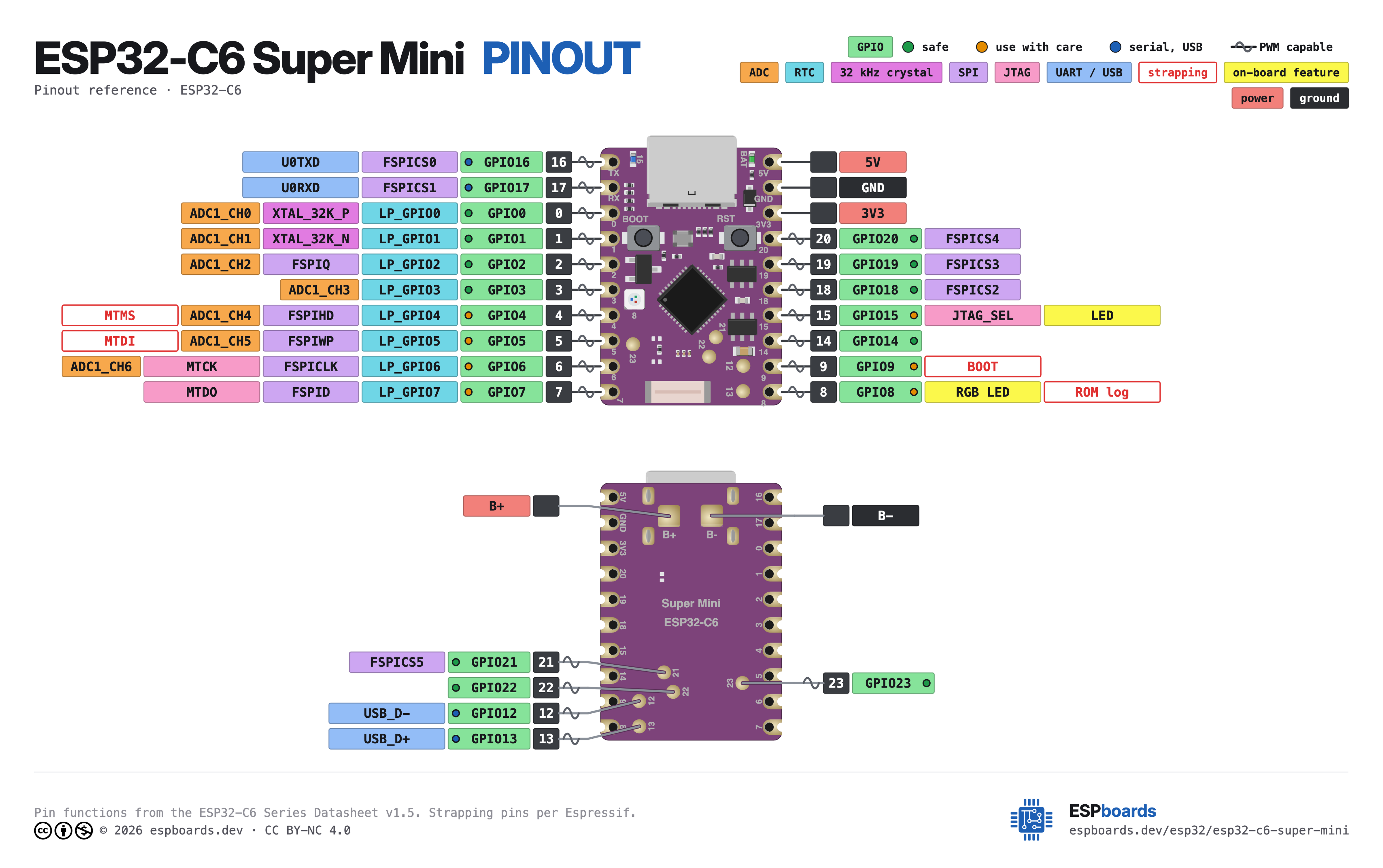
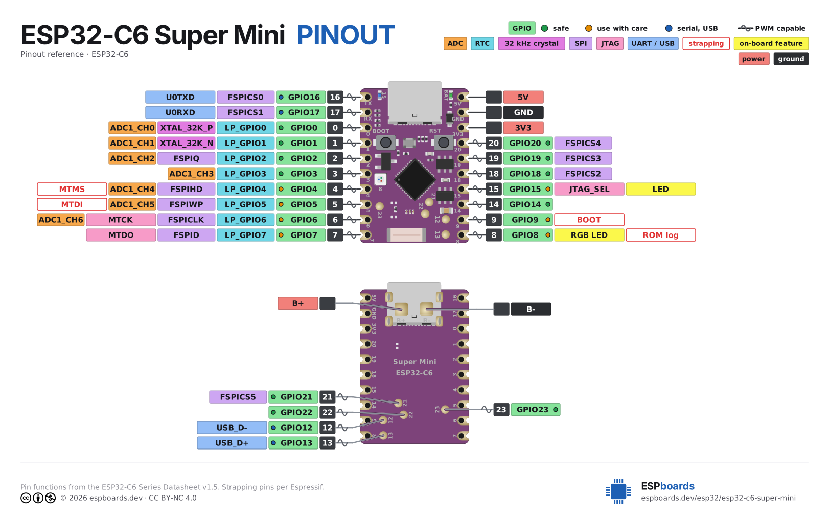
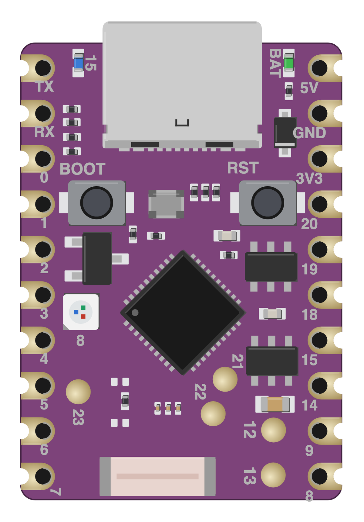
Every pin on both sides of the board with its functions, drawn by ESPboards from the ESP32-C6 Series Datasheet v1.5 - the same sheet shown at the top of this page. The PNG is a high-resolution image for screens, the SVG is vector so it stays sharp at any size, and the PDF is laid out to print on A4 or Letter.
Yours to use, share and adapt for non-commercial work, as long as you credit espboards.dev - the full terms and ready-made credit lines are here.
Specifications
ESP32-C6 · 25.56 × 18 mm · vs other ESP32 chips →Dimensions

About this board
Inside sits the ESP32-C6 - a RISC-V part adding Wi-Fi 6 plus Thread/Zigbee radios. Sibling Super Mini boards cover the ESP32-C3, ESP32-H2 and ESP32-S3, so you can change radios or horsepower without changing the footprint.
It's the only ESP32-C6 option in the Super Mini family.
The $5.00 price tag is typical for a Super Mini board.
Around the module: an addressable RGB LED (GPIO8), status LEDs (Power, Status) and Reset/Boot buttons.
It flashes over native USB - no serial-converter driver needed.
The ESP32-C6 SuperMini is a compact and powerful development board featuring the Espressif ESP32-C6 WiFi 6 and Bluetooth dual-mode chip. With support for IEEE 802.11ax WiFi 6 (2.4 GHz) and Bluetooth 5 (LE) with Bluetooth Mesh, it ensures fast and reliable wireless connectivity. On top of that sits the C6's party trick: an IEEE 802.15.4 radio for Zigbee 3.0 and Thread, making this one of the smallest boards that can join a Zigbee network or act as a Matter-over-Thread device.
At its core, the ESP32-C6 SuperMini is powered by a RISC-V 32-bit single-core processor running at up to 160 MHz, offering efficient performance for IoT applications. It includes 512 KB of high-performance SRAM, 16 KB of low-power SRAM, and 4 MB of flash memory, giving your projects plenty of space to run smoothly.
Designed with ease of use in mind, the board comes with a USB Type-C interface for simple programming and connectivity. Plus, its compact form factor makes it ideal for space-constrained applications.
With versatile interfaces (UART, I2C, SPI) and a rich set of GPIOs, the ESP32-C6 SuperMini is a great choice.
Wondering how the ESP32-C6 SuperMini compares to other SuperMini boards? Check out our full comparison guide to see how it stacks up against the C3, C3 Plus, S3, and H2.
- Ultra-small size for embedded applications
- Ultra-low power consumption with low-power working modes
- RISC-V 32-bit single-core CPU running at up to 160 MHz
- 512 KB high-performance SRAM and 16 KB low-power SRAM
- WiFi 6 (802.11ax, 2.4 GHz) with 40 MHz bandwidth support
- Bluetooth 5 (LE) and Bluetooth Mesh support
- IEEE 802.15.4 radio for Zigbee 3.0, Thread, and Matter-over-Thread
- Battery pads with LTH7R lithium charging circuit
- USB Type-C interface for programming and connectivity
- Stamp hole design for direct soldering onto PCB
Where to buy
prices are typical street pricesResources
Similar boards
All Supermini boards →

