
ESP32 C3 Super Mini Plus
Slightly larger ESP32-C3 board with better layout and I/O - perfect for battery-powered and wireless builds.

Pinout
16 pins · 2.54 mm pitch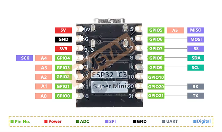
| Pin | GPIO | Labels | Status | Capabilities | Notes |
|---|---|---|---|---|---|
| 1 | - | 5V | power | - | 5V power input for the board |
| 2 | - | GND | ground | - | Ground connection |
| 3 | - | 3V33.3V | power | - | 3.3V power output |
| 4 | 0 | IO0A0 | safe | adc · pwm | GPIO, ADC pin, PWM |
| 5 | 1 | IO1A1 | safe | adc · pwm | GPIO, ADC pin, PWM |
| 6 | 2 | IO2A2 | strapping | adc · pwm | GPIO, ADC pin, PWM |
| 7 | 3 | IO3A3 | safe | adc · pwm | GPIO, ADC pin, PWM |
| 8 | 4 | IO4A4 | strapping | adc · pwm | GPIO, ADC pin, SCK, PWM |
| 9 | 5 | IO5A5 | strapping | adc · spi · pwm | GPIO, ADC pin, SPI Master In Slave Out, PWM |
| 10 | 6 | IO6MISO | strapping | spi · pwm | GPIO, SPI Master Out Slave In, PWM |
| 11 | 7 | IO7SS | strapping | spi · pwm | GPIO, SPI Slave Select, PWM |
| 12 | 8 | IO8SDA | strapping | i2c · pwm | GPIO, I2C Data line, PWM |
| 13 | 9 | IO9SCL | strapping | i2c · pwm | GPIO, I2C Clock line, PWM |
| 14 | 10 | IO10RX | uart | uart · pwm | GPIO, PWM |
| 15 | 21 | IO21TX | uart | uart | GPIO, UART Transmit |
| 16 | 20 | IO20RX | uart | uart | GPIO, UART Receive (secondary) |
Start with these
4 pins with no boot or system involvementFreely assignable - no strapping, flash, USB or JTAG duties. Ideal first picks for buttons, sensors and LEDs.
Fine - with a little care
sampled at boot or shared with debug/serial| Pin | Label | What to know | Role |
|---|---|---|---|
| IO2 | GPIO2 | Must be held high during boot (if low on reset, normal flash boot may fail) | Strapping |
| IO4 | MTMS | Used during boot; JTAG TMS for debugging; acts as Quad-SPI flash IO (hold data line) in internal-flash variants | JTAG |
| IO5 | MTDI | Used during boot; JTAG TDI for debugging; acts as Quad-SPI flash IO (write-protect data line) in internal-flash variants | JTAG |
| IO6 | MTCK | Used during boot; JTAG TCK for debugging; provides flash clock in internal-flash variants | JTAG |
| IO7 | MTDO | Used during boot; JTAG TDO for debugging; acts as Quad-SPI flash IO (data line) in internal-flash variants | JTAG |
| IO8 | GPIO8 | Must be held high during reset (if low, UART flashing/boot may not work) | Strapping |
| IO9 | GPIO9 | Controls boot mode on reset (HIGH for normal flash boot, LOW enters serial download mode) | Strapping |
| IO21 | U0TXD | Used as UART0 transmit (console/bootloader); repurposing may disable serial console output and printing | UART |
| IO20 | U0RXD | Used as UART0 receive (console/bootloader); repurposing may disable serial programming and debug logs | UART |
Pinout notes The ESP32 C3 Super Mini Plus breaks out 16 pins in total: 13 GPIO for your project, with 5V, GND and 3V3 handling power. Peripheral wiring is straightforward:…
The ESP32 C3 Super Mini Plus breaks out 16 pins in total: 13 GPIO for your project, with 5V, GND and 3V3 handling power.
Peripheral wiring is straightforward: I²C is mapped to SDA on GPIO8 and SCL on GPIO9, while TX/RX on GPIO21 and GPIO10 cover serial logging and flashing.
Beyond plain digital I/O you get 6 ADC-capable pins for sensors and battery monitoring and PWM on 11 pins.
9 of the exposed pins carry boot-time or system duties on the ESP32-C3 (IO2, IO4, IO5 and 6 more) - check the guidance above before wiring anything to them. IO0, IO1, IO3 and IO10 are free of any such role - the safest first picks.
Guides & tutorials

Getting started
flash your first firmware in ~2 minutesBoard: ESP32C3 Dev Module USB CDC On Boot: Enabled Flash Size: 4MB (32Mb) Flash Mode: QIO Partition Scheme: Default 4MB with spiffs (1.2MB APP/1.5MB SPIFFS) Upload Speed: 921600
// toggle GPIO0 - wire an LED and resistor to it
void setup() {
  pinMode(0, OUTPUT);
}
void loop() {
  digitalWrite(0, HIGH); delay(500);
  digitalWrite(0, LOW);  delay(500);
}[env:esp32-c3-super-mini-plus]
platform = espressif32
board = esp32-c3-devkitm-1
framework = arduino
monitor_speed = 115200
upload_speed = 921600esp32-c3-devkitm-1 - or type it after board =.esp32:
board: esp32-c3-devkitm-1
variant: esp32c3
framework:
type: esp-idf
# blink - GPIO0
output:
- platform: gpio
pin: 0
id: led_out
light:
- platform: binary
name: "LED"
output: led_outesp32-c3-devkitm-1 (same ids as PlatformIO).esptool.py --chip esp32c3 --port /dev/ttyACM0 \
--baud 921600 write_flash 0x0 firmware.bin--port = your /dev/tty* (macOS/Linux) or COMx (Windows).Good to know
board-specific quirks worth 60 seconds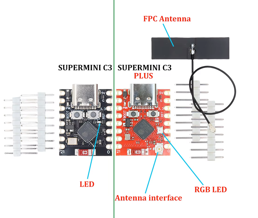
The standard C3 SuperMini's weak ceramic antenna is its best-documented flaw - and the Plus is the variant that answers it. Instead of relying on the onboard antenna, it adds a U.FL connector and typically ships with an FPC antenna in the bag, taking the board's most common complaint off the table entirely. Telling the two apart is easy: the Plus is the red PCB with the U.FL socket in the corner and a WS2812 RGB LED…
The standard C3 SuperMini's weak ceramic antenna is its best-documented flaw - and the Plus is the variant that answers it. Instead of relying on the onboard antenna, it adds a U.FL connector and typically ships with an FPC antenna in the bag, taking the board's most common complaint off the table entirely.
Telling the two apart is easy: the Plus is the red PCB with the U.FL socket in the corner and a WS2812 RGB LED on GPIO8, where the standard C3 is black with a single blue LED. Same chip, same pinout, same code on both.
If long range is the goal, this is the SuperMini to buy - no antenna surgery required. Got the black board instead? Its antenna can still be fixed with a wire mod.
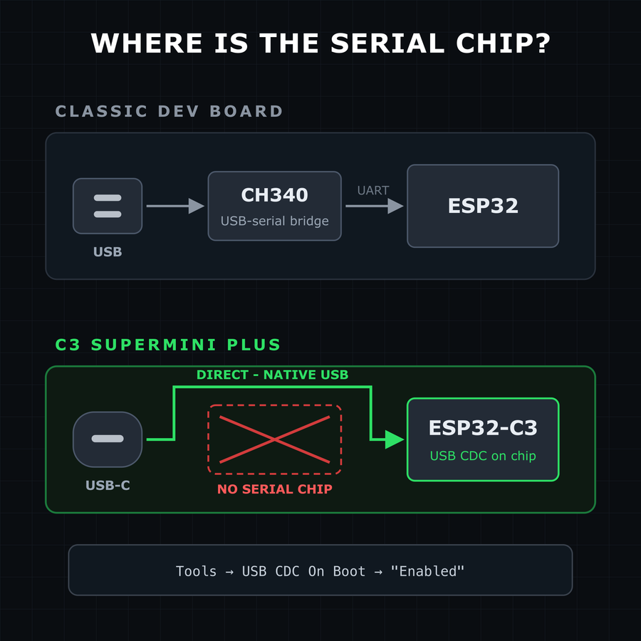
Like all the SuperMinis, the Plus has no USB-to-serial converter chip - USB-C connects straight to the ESP32-C3's native USB. Two everyday consequences: Serial output: enable Tools → USB CDC On Boot → "Enabled" in Arduino IDE, or Serial.print() goes to the UART pins instead of your serial monitor. Flashing: if the COM port never appears or an upload fails, hold BOOT while plugging in USB (or while tapping RESET) to…
Like all the SuperMinis, the Plus has no USB-to-serial converter chip - USB-C connects straight to the ESP32-C3's native USB. Two everyday consequences:
- Serial output: enable Tools → USB CDC On Boot → "Enabled" in Arduino IDE, or
Serial.print()goes to the UART pins instead of your serial monitor. - Flashing: if the COM port never appears or an upload fails, hold BOOT while plugging in USB (or while tapping RESET) to force the ROM bootloader, then press RESET after flashing.
A crashed or deep-sleeping sketch takes the USB port down with it - normal for native-USB boards, not a broken board. The BOOT-button trick always recovers it.
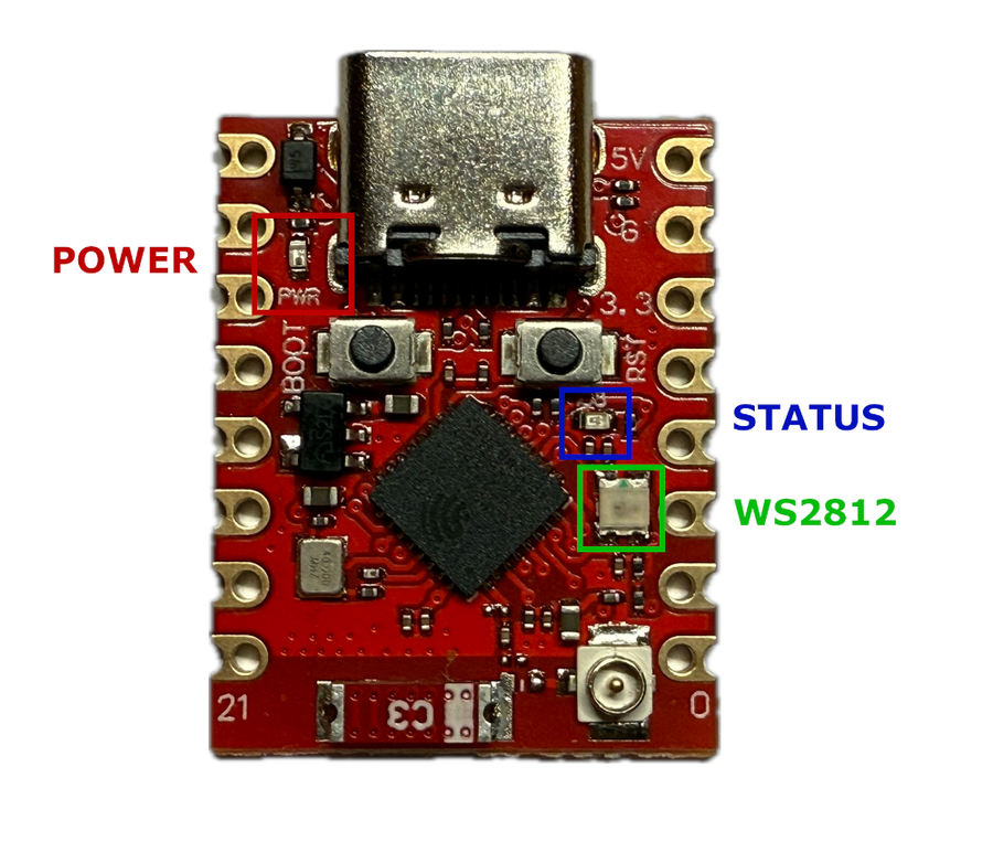
The ESP32-C3 Supermini Plus features three onboard LEDs: a power indicator, a user-controllable blue LED, and a WS2812 RGB LED. Note that the Blue LED and WS2812 share GPIO8, which can lead to conflicts if used simultaneously. Here's a breakdown of each LED's function, GPIO assignment, and usage examples. Red LED - Power Indicator GPIO: None Control: Not controllable via GPIO Behavior: Always on when the board is…
The ESP32-C3 Supermini Plus features three onboard LEDs: a power indicator, a user-controllable blue LED, and a WS2812 RGB LED. Note that the Blue LED and WS2812 share GPIO8, which can lead to conflicts if used simultaneously. Here's a breakdown of each LED's function, GPIO assignment, and usage examples.
Red LED - Power Indicator
- GPIO:
None - Control: Not controllable via GPIO
- Behavior: Always on when the board is powered
Blue LED - User Controllable
- GPIO:
GPIO8 - Control:
digitalWrite(), ESPHome GPIO output - Both the Blue LED and WS2812 share GPIO8 and use different signal types (digital vs. timing-based), which means they cannot be reliably used at the same time.
void setup() {
  pinMode(8, OUTPUT);
}

void loop() {
  digitalWrite(8, HIGH);
  delay(1000);
  digitalWrite(8, LOW);
  delay(1000);
}
output:
  - platform: gpio
    pin: 8
    id: blue_led

light:
  - platform: binary
    name: "Blue LED"
    output: blue_led
WS2812 LED - Programmable RGB
- GPIO:
GPIO8 - Control: Adafruit NeoPixel library (recommended)
- Both the Blue LED and WS2812 share GPIO8 and use different signal types (digital vs. timing-based), which means they cannot be reliably used at the same time.
#include

#define PIN        8
#define NUMPIXELS  1

Adafruit_NeoPixel pixels(NUMPIXELS, PIN, NEO_GRB + NEO_KHZ800);

void setup() {
  pixels.begin();
}

void loop() {
  pixels.setPixelColor(0, pixels.Color(255, 0, 0));
  pixels.show();
  delay(1000);

  pixels.setPixelColor(0, pixels.Color(0, 255, 0));
  pixels.show();
  delay(1000);

  pixels.setPixelColor(0, pixels.Color(0, 0, 255));
  pixels.show();
  delay(1000);
}
light:
  - platform: neopixelbus
    type: GRB
    pin: 8
    num_leds: 1
name: "Onboard RGB LED"Specifications
ESP32-C3 · 22.5 × 18 mm · vs other ESP32 chips →About this board
At 22.5 × 18 mm it's the smallest Super Mini board we've measured.
Inside sits the ESP32-C3 - a single-core RISC-V and the budget low-power pick. Sibling Super Mini boards cover the ESP32-C6, ESP32-H2 and ESP32-S3, so you can change radios or horsepower without changing the footprint.
The $5.00 price tag is typical for a Super Mini board.
Around the module: an addressable RGB LED (GPIO8), status LEDs (Power, User) and Reset/Boot buttons.
It flashes over native USB - no serial-converter driver needed.
If you have the black pcb board, check ESP32 C3 Supermini
The ESP32-C3 SuperMini Plus is an enhanced IoT mini development board based on the Espressif ESP32-C3 WiFi/Bluetooth dual-mode chip. It shares the same core architecture as the standard SuperMini, featuring a 32-bit RISC-V CPU, 400 KB of SRAM, and 4 MB of flash memory. The board supports IEEE 802.11b/g/n WiFi and Bluetooth 5 (LE) protocols, ensuring robust connectivity.
A key difference between the two models is the antenna design. The SuperMini features a built-in small PCB antenna, whereas the SuperMini Plus comes with an external antenna that connects to the board via a U.FL connector, offering better range and signal strength for wireless applications.
The SuperMini Plus also comes in a distinct red PCB variant and features an onboard RGB LED, allowing for more flexible LED control compared to the single blue LED on the original SuperMini. This RGB LED enables users to program different colors for status indications, making it more versatile for IoT and embedded projects.
Wondering how the ESP32-C3 SuperMini Plus compares to other SuperMini boards? Check out our full comparison guide to see how it stacks up against the C3, S3, C6, and H2.
- Red PCB variant
- Ultra-low power consumption: deep sleep power consumption of about 43μA
- Onboard RGB LED for multi-color status indication
- External U.FL/IPEX antenna connector for improved WiFi range (solder the jumper pad to enable)
Where to buy
prices are typical street prices
Resources
Similar boards
All Supermini boards →

