
ESP32-H2 Super Mini
Ultra-compact ESP32-H2 board with BLE and Thread - ideal for low-power mesh networks and Matter-ready IoT devices.

ESP32-H2 Super Mini Pinout
22 pins · 2.54 mm pitch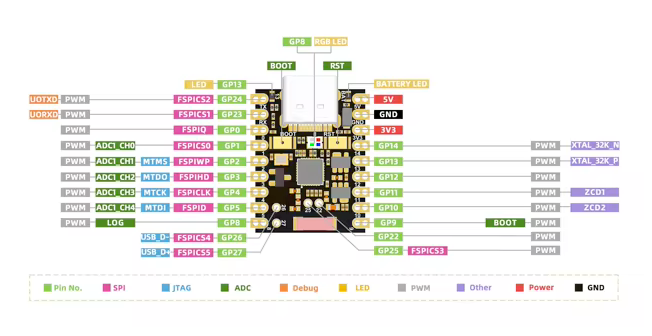
| Pin | GPIO | Labels | Status | Capabilities | Notes |
|---|---|---|---|---|---|
| 1 | - | 5V | power | - | 5V power input for the board |
| 2 | - | GND | ground | - | Ground connection |
| 3 | - | 3V33.3V | power | - | 3.3V power output for peripherals |
| 4 | 0 | IO0GP0 | strapping | - | GPIO |
| 5 | 1 | IO1GP1 | strapping | adc | GPIO, ADC pin |
| 6 | 2 | IO2GP2 | strapping | adc | GPIO, ADC pin |
| 7 | 3 | IO3GP3 | strapping | adc | GPIO, ADC pin |
| 8 | 4 | IO4GP4 | strapping | adc | GPIO, ADC pin |
| 9 | 5 | IO5GP5 | strapping | adc | GPIO, ADC pin |
| 10 | 8 | IO8GP8 | strapping | - | GPIO, LOG |
| 11 | 9 | IO9GP9 | strapping | - | GPIO, BOOT |
| 12 | 10 | IO10GP10 | safe | - | GPIO |
| 13 | 11 | IO11GP11 | safe | - | GPIO |
| 14 | 12 | IO12GP12 | safe | - | GPIO |
| 15 | 13 | IO13GP13 | safe | - | GPIO, LED |
| 16 | 14 | IO14GP14 | safe | - | GPIO |
| 17 | 22 | IO22GP22 | safe | - | GPIO |
| 18 | 24 | TXIO24 | uart | uart | TX |
| 19 | 23 | IO23GP23 | uart | - | GPIO |
| 20 | 25 | IO25GP25 | strapping | - | GPIO |
| 21 | 26 | IO26GP26 | uart | - | GPIO |
| 22 | 27 | IO27GP27 | uart | - | GPIO |
Start with these
6 pins with no boot or system involvementFreely assignable - no strapping, flash, USB or JTAG duties. Ideal first picks for buttons, sensors and LEDs.
Fine - with a little care
11 pins · 10 things to knowIO0IO1 General-purpose SPI2 (FSPI) IO MUX pins Other
IO MUX pin of the general-purpose SPI2 (FSPI) bus. The H2 runs its in-package flash on GPIO15-20, which the QFN32 package does not route out, so this pin is free unless your board wires an SPI peripheral to FSPI.
- IO0General-purpose SPI2 (FSPI) IO MUX pin - data out (FSPIQ)
- IO1General-purpose SPI2 (FSPI) IO MUX pin - chip select (FSPICS0)
IO2 JTAG TMS signal; also the general-purpose SPI2 (FSPI) write-protect/data line (FSPIWP) JTAG
Default JTAG TMS line - using it as GPIO disables external JTAG debugging. It is not a flash pin: the H2 keeps its in-package flash on GPIO15-20, which the QFN32 package does not route out.
IO3 JTAG TDO signal; also the general-purpose SPI2 (FSPI) hold/data line (FSPIHD) JTAG
Default JTAG TDO line - using it as GPIO disables external JTAG debugging. It is not a flash pin: the H2 keeps its in-package flash on GPIO15-20, which the QFN32 package does not route out.
IO4 JTAG TCK signal; also the general-purpose SPI2 (FSPI) clock (FSPICLK) JTAG
Default JTAG TCK line - using it as GPIO disables external JTAG debugging. It is not a flash pin: the H2 keeps its in-package flash on GPIO15-20, which the QFN32 package does not route out.
IO5 JTAG TDI signal; also the general-purpose SPI2 (FSPI) data in (FSPID) JTAG
Default JTAG TDI line - using it as GPIO disables external JTAG debugging. It is not a flash pin: the H2 keeps its in-package flash on GPIO15-20, which the QFN32 package does not route out.
IO8 Bootstrapping pin; controls chip boot mode and ROM debug message printing. Strapping
Must be held at the proper logic level on reset to select the correct boot mode and enable/disable bootloader log output.
IO9 Bootstrapping pin; controls chip boot mode (with GPIO8). Strapping
Must be pulled high on reset for normal SPI flash boot (pulling it low while GPIO8 is high forces the chip into download/programming mode).
TXGPIO24 UART0 TXD (transmit) pin, default serial console output. UART
Often used for boot log output and serial debugging; repurposing it can disable serial output of boot messages and interfere with console debugging.
IO23 UART0 RXD (receive) pin, default serial console input. UART
Often used for the serial console and bootloader input; repurposing it may conflict with UART communication for programming or debugging.
IO25 Bootstrapping pin; selects JTAG signal source (USB Serial/JTAG controller vs. external JTAG). Strapping
Used during boot to determine the JTAG interface source; this pin has no internal pull-up/down, so it must not be left floating (an external resistor drives it high/low to avoid unintended JTAG mode selection).
Only if you know the tricks
2 pins · 2 things to knowIO26 USB D- connection pin (USB Serial/JTAG controller interface). USB
By default, this pin is connected to the chip's internal USB Serial/JTAG peripheral; using it as a general-purpose IO requires disabling or reconfiguring that USB interface.
IO27 USB D+ connection pin (with internal USB pull-up). USB
By default, this pin is connected to the internal USB Serial/JTAG controller; using it as a general-purpose IO would disable the USB functionality used for debugging/programming.
The ESP32-H2 Super Mini breaks out 22 pins in total: 19 GPIO for your project, with 5V, GND and 3V3 handling power.
On the analog side there are 5 ADC-capable pins for sensors and battery monitoring.
If you want zero surprises, IO10, IO11, IO12, IO13 and 2 more are free of any such role - the safest first picks. 11 of the exposed pins carry boot-time or system duties on the ESP32-H2 (IO0, IO1, IO2 and 8 more).
Guides & tutorials

Getting started
flash your first firmware in ~2 minutesBoard: ESP32H2 Dev Module USB CDC On Boot: Enabled Flash Size: 4MB (32Mb) Flash Mode: QIO Partition Scheme: Default 4MB with spiffs (1.2MB APP/1.5MB SPIFFS) Upload Speed: 921600
// toggle GPIO10 - wire an LED and resistor to it
void setup() {
  pinMode(10, OUTPUT);
}
void loop() {
  digitalWrite(10, HIGH); delay(500);
  digitalWrite(10, LOW);  delay(500);
}[env:esp32-h2-super-mini]
platform = https://github.com/pioarduino/platform-espressif32/releases/download/stable/platform-espressif32.zip
board = esp32-h2-devkitm-1
framework = arduino
monitor_speed = 115200
upload_speed = 921600esp32-h2-devkitm-1 - or type it after board =.esp32:
board: esp32-h2-devkitm-1
variant: esp32h2
framework:
type: esp-idf
# blink - GPIO10
output:
- platform: gpio
pin: 10
id: led_out
light:
- platform: binary
name: "LED"
output: led_outesp32-h2-devkitm-1 (same ids as PlatformIO).esptool.py --chip esp32h2 --port /dev/ttyACM0 \
--baud 921600 write_flash 0x0 firmware.bin--port = your /dev/tty* (macOS/Linux) or COMx (Windows).Good to know
board-specific quirks worth 60 seconds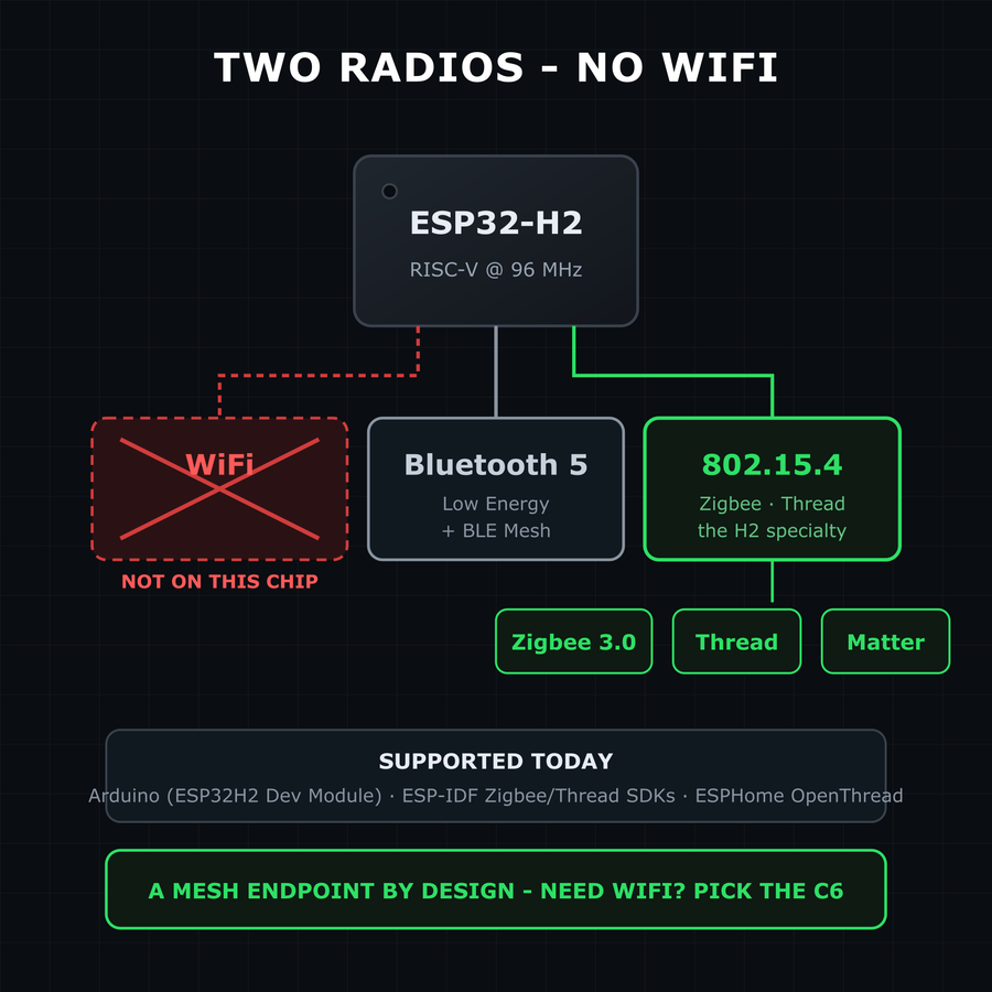
Read this before buying: unlike every other ESP32, the ESP32-H2 has no WiFi radio at all. What it has instead is Bluetooth 5 LE and an IEEE 802.15.4 radio for Zigbee 3.0, Thread, and Matter-over-Thread. If your project needs to talk to a WiFi network directly, pick the C6 SuperMini - it has all three radios. That's not a flaw, it's the niche: the H2 is built to be a low-power mesh endpoint - a Zigbee sensor, a…
Read this before buying: unlike every other ESP32, the ESP32-H2 has no WiFi radio at all. What it has instead is Bluetooth 5 LE and an IEEE 802.15.4 radio for Zigbee 3.0, Thread, and Matter-over-Thread. If your project needs to talk to a WiFi network directly, pick the C6 SuperMini - it has all three radios.
That's not a flaw, it's the niche: the H2 is built to be a low-power mesh endpoint - a Zigbee sensor, a Thread node - where a border router or hub bridges to your network. Tooling is the same as the C6's 802.15.4 side: ESP-IDF Zigbee/Thread SDKs, Arduino via the standard ESP32 core, and ESPHome's OpenThread support.
No WiFi also means no OTA-over-WiFi, no web dashboards, no MQTT-over-WiFi - plan your architecture around the mesh.
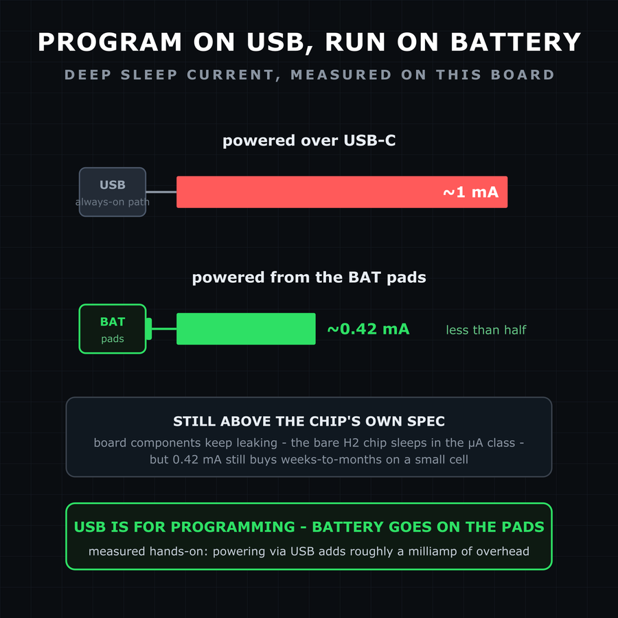
The H2 SuperMini has battery solder pads, and a hands-on measurement on this exact board puts deep sleep at about 0.42 mA when powered through the BAT pads - and roughly 1 mA more via USB, since the USB path keeps extra circuitry awake. Honest framing: 420 µA is far above the H2 chip's own microamp-class sleep spec - board components still leak - but it's an order of magnitude better than classic dev boards, enough…
The H2 SuperMini has battery solder pads, and a hands-on measurement on this exact board puts deep sleep at about 0.42 mA when powered through the BAT pads - and roughly 1 mA more via USB, since the USB path keeps extra circuitry awake.
Honest framing: 420 µA is far above the H2 chip's own microamp-class sleep spec - board components still leak - but it's an order of magnitude better than classic dev boards, enough for weeks-to-months on a small cell depending on wake cadence.
For the lowest draw, power the board from the battery pads and treat USB as a programming connector, not a power strategy.
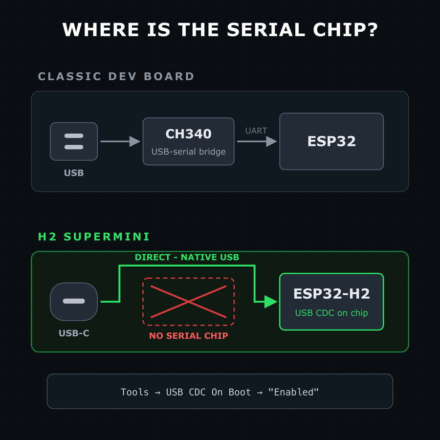
Like the other SuperMinis, the H2 has no USB-to-serial converter chip - USB-C connects straight to the ESP32-H2's native USB. Two everyday consequences: Serial output: enable Tools → USB CDC On Boot → "Enabled" in Arduino IDE, or Serial.print() goes to the UART pins instead of your serial monitor. Flashing: if the COM port never appears or an upload fails, hold BOOT while plugging in USB (or while tapping RESET) to…
Like the other SuperMinis, the H2 has no USB-to-serial converter chip - USB-C connects straight to the ESP32-H2's native USB. Two everyday consequences:
- Serial output: enable Tools → USB CDC On Boot → "Enabled" in Arduino IDE, or
Serial.print()goes to the UART pins instead of your serial monitor. - Flashing: if the COM port never appears or an upload fails, hold BOOT while plugging in USB (or while tapping RESET) to force the ROM bootloader, then press RESET after flashing.
A crashed or deep-sleeping sketch takes the USB port down with it - normal for native-USB boards, not a broken board. The BOOT-button trick always recovers it.
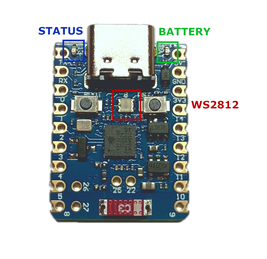
The ESP32-H2 Supermini features three onboard LEDs: a green battery indicator, a user-controllable blue LED, and a WS2812 RGB LED. Note that the Blue LED and WS2812 share GPIO13 and GPIO8 respectively, and may interfere if both are driven simultaneously due to signal timing constraints. Green LED - Battery Charge Indicator GPIO: None Control: Not controllable via GPIO Behavior: Charging → LED on Battery connected →…
The ESP32-H2 Supermini features three onboard LEDs: a green battery indicator, a user-controllable blue LED, and a WS2812 RGB LED. Note that the Blue LED and WS2812 share GPIO13 and GPIO8 respectively, and may interfere if both are driven simultaneously due to signal timing constraints.
Green LED - Battery Charge Indicator
- GPIO:
None - Control: Not controllable via GPIO
- Behavior:
- Charging → LED on
- Battery connected → LED off
- No battery → LED blinks
Blue LED - User Controllable
- GPIO:
GPIO13 - Control:
digitalWrite(), ESPHome GPIO output
void setup() {
  pinMode(13, OUTPUT);
}

void loop() {
  digitalWrite(13, HIGH);
  delay(1000);
  digitalWrite(13, LOW);
  delay(1000);
}
output:
  - platform: gpio
    pin: 13
    id: blue_led

light:
  - platform: binary
    name: "Blue LED"
    output: blue_led
WS2812 LED - Programmable RGB
- GPIO:
GPIO8 - Control: FastLED, NeoPixel, etc.
#include <FastLED.h>

#define NUM_LEDS 1
#define DATA_PIN 8

CRGB leds[NUM_LEDS];

void setup() {
  FastLED.addLeds<NEOPIXEL, DATA_PIN>(leds, NUM_LEDS);
}

void loop() {
  leds[0] = CRGB::Red; FastLED.show(); delay(1000);
  leds[0] = CRGB::Green; FastLED.show(); delay(1000);
  leds[0] = CRGB::Blue; FastLED.show(); delay(1000);
light:
  - platform: neopixelbus
    type: GRB
    pin: 8
    num_leds: 1
name: "Onboard RGB LED"Specifications
ESP32-H2 · 23 × 18 mm · vs other ESP32 chips →Dimensions
About this board
At 23 × 18 mm it's among the smallest boards in the whole ESP32 family.
Inside sits the ESP32-H2 - a Thread/Zigbee-focused RISC-V with no Wi-Fi at all. Sibling Super Mini boards cover the ESP32-C3, ESP32-C6 and ESP32-S3, so you can change radios or horsepower without changing the footprint.
It's the only ESP32-H2 option in the Super Mini family.
Expect to pay about $5.00 - in line with other Super Mini boards.
Onboard you'll find an addressable RGB LED (GPIO8) and Reset/Boot buttons.
It flashes over native USB - no serial-converter driver needed.
The ESP32-H2 SuperMini is an ultra-low-power IoT development board based on the Espressif ESP32-H2 chip. It features a 32-bit RISC-V single-core processor running at up to 96 MHz. The board integrates IEEE 802.15.4 support, making it compatible with Thread and Zigbee protocols for robust mesh networking. Additionally, it includes Bluetooth Low Energy (BLE) and operates in the 2.4 GHz band with a data rate of up to 250 Kbps. The ESP32-H2 SuperMini is designed for applications requiring low-power consumption, RF stability, and secure wireless communication, making it ideal for IoT, smart home, and industrial automation.
Wondering how the ESP32-H2 SuperMini compares to other SuperMini boards? Check out our full comparison guide to see how it stacks up against the C3, C3 Plus, S3, and C6.
- No Wi-Fi radio - 802.15.4 (Thread, Zigbee, Matter) plus Bluetooth LE only
- RISC-V 32-bit single-core CPU running at up to 96 MHz
- 128 KB ROM, 320 KB SRAM, 4 KB Low-Power SRAM
- 4 MB in-package flash memory (no PSRAM)
- Supports IEEE 802.15.4 (Thread and Zigbee)
- Bluetooth 5 Low Energy (BLE) support
- Operates in the 2.4 GHz band with 250 Kbps data rate
- USB Type-C interface for easy programming
- Low-power consumption for battery-operated devices
Where to buy
prices are typical street pricesResources
Similar boards
All Supermini boards →

