
Waveshare ESP32-S3-Touch-LCD-4B
Waveshare 86-box smart panel: ESP32-S3 N16R8 with a 4in 480x480 IPS touch LCD, dual mics, speaker amp, IMU, RTC and AXP2101 battery management.

Waveshare ESP32-S3-Touch-LCD-4B Pinout
20 pins · 2 mm pitch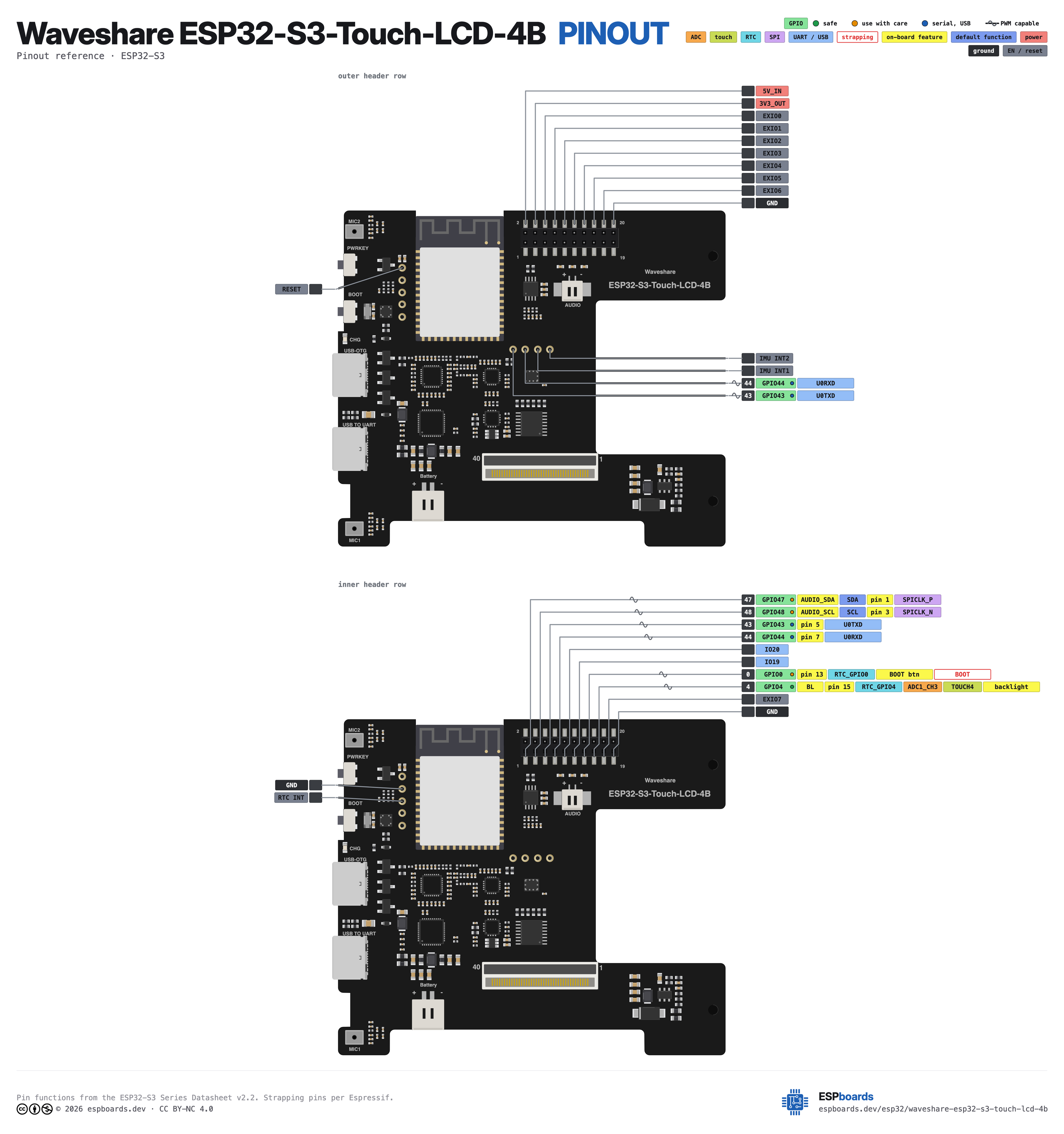
| Pin | GPIO | Labels | Status | Capabilities | Notes |
|---|---|---|---|---|---|
| 1 | - | 5V_INVBUSpin 2 | power | - | 5 V rail shared with both USB-C VBUS lines; feed 5 V here to power the board |
| 2 | 47 | AUDIO_SDAGPIO47SDApin 1 | strapping | i2c · pwm | Board-wide I2C SDA shared by touch, IO expander, codec, mic ADC, IMU, RTC and PMIC |
| 3 | - | 3V3_OUTVCC_3V3pin 4 | power | - | 3.3 V output from the AXP2101 |
| 4 | 48 | AUDIO_SCLGPIO48SCLpin 3 | strapping | i2c · pwm | Board-wide I2C SCL, same shared bus as SDA |
| 5 | - | EXIO0pin 6 | control | - | TCA9554 expander P0, LCD SPI chip select during ST7701 init |
| 6 | 43 | TX0GPIO43U0TXDpin 5 | uart | uart · pwm | UART0 TX, also wired to the CH343P USB-UART bridge |
| 7 | - | EXIO1pin 8 | control | - | TCA9554 expander P1, LCD SPI data line during ST7701 init |
| 8 | 44 | RX0GPIO44U0RXDpin 7 | uart | uart · pwm | UART0 RX, also driven by the CH343P USB-UART bridge |
| 9 | - | EXIO2pin 10 | control | - | TCA9554 expander P2, LCD SPI clock during ST7701 init |
| 10 | 20 | IO20GPIO20USB_D+pin 9 | usb | adc · pwm | Native USB D+, shared with the USB-OTG port; ADC2 so no ADC while Wi-Fi is on |
| 11 | - | EXIO3pin 12 | control | - | TCA9554 expander P3, speaker amplifier enable |
| 12 | 19 | IO19GPIO19USB_D-pin 11 | usb | adc · pwm | Native USB D-, shared with the USB-OTG port; ADC2 so no ADC while Wi-Fi is on |
| 13 | - | EXIO4pin 14 | control | - | TCA9554 expander P4, reads the PWR key (low while pressed) |
| 14 | 0 | IO0GPIO0BOOTpin 13 | strapping | pwm | BOOT button, strapping pin |
| 15 | - | EXIO5pin 16 | control | - | TCA9554 expander P5, touch controller reset (TP_RST) |
| 16 | 4 | BLGPIO4pin 15 | safe | adc · touch · pwm | LCD backlight PWM into the AP3032 LED driver |
| 17 | - | EXIO6pin 18 | control | - | TCA9554 expander P6, touch interrupt input (TP_INT), readable only over I2C |
| 18 | - | EXIO7pin 17 | control | - | TCA9554 expander P7, LCD panel reset (RST) |
| 19 | - | GNDpin 20 | ground | - | Ground |
| 20 | - | GNDpin 19 | ground | - | Ground |
Start with these
1 pins with no boot or system involvementFreely assignable - no strapping, flash, USB or JTAG duties. Ideal first picks for buttons, sensors and LEDs.
Fine - with a little care
5 pins · 4 things to knowAUDIO_SDAGPIO47AUDIO_SCLGPIO48 Octal SPI differential clock legs (SPICLK_P/N_DIFF), used only by the 1.8 V octal flash/PSRAM variants Other
Only the 1.8 V octal parts (ESP32-S3R8V, ESP32-S3R16V) run the differential memory clock here, and on those the pin works at 1.8 V instead of 3.3 V. On the common 3.3 V modules it is a normal GPIO - several devkits drive their RGB LED from GPIO48.
- AUDIO_SDAOctal SPI differential clock positive leg (SPICLK_P_DIFF), used only by the 1.8 V octal flash/PSRAM variants
- AUDIO_SCLOctal SPI differential clock negative leg (SPICLK_N_DIFF), used only by the 1.8 V octal flash/PSRAM variants
TX0GPIO43 UART0 transmit pin (U0TXD), default serial console TX UART
Used for bootloader output and UART console logs. If repurposed, you will lose the default serial output (and programming via UART0).
RX0GPIO44 UART0 receive pin (U0RXD), default serial console RX UART
Used for bootloader input (download mode via serial). If repurposed, you cannot use the default UART0 download mode for programming the chip.
IO0 Bootstrapping pin (Chip boot mode selection) Strapping
Must be pulled high (default) or low (to enter UART download mode) at reset. Using it for other functions can interfere with boot mode configuration.
Only if you know the tricks
2 pins · 1 thing to knowIO20IO19 USB OTG differential data pair (D- and D+) USB
By default connected to the on-chip USB Serial/JTAG controller. Using it as general GPIO without reconfiguring IO MUX will interfere with USB functionality.
- IO20USB OTG positive differential data line (USB_D+)
- IO19USB OTG negative differential data line (USB_D-)
The Waveshare ESP32-S3-Touch-LCD-4B breaks out 20 pins in total: 6 GPIO for your project, with 5V_IN, 3V3_OUT and GND handling power.
For peripherals, I²C is mapped to SDA on GPIO47 and SCL on GPIO48.
On the analog side there is 1 ADC-capable pin for sensors and battery monitoring, PWM on every GPIO and 1 capacitive-touch inputs.
If you want zero surprises, BL is free of any such role - the safest first picks. 5 of the exposed pins carry boot-time or system duties on the ESP32-S3 (AUDIO_SDA, AUDIO_SCL, TX0 and 2 more).
Pinout notes There are no spare ESP32-S3 GPIOs on this board: the RGB panel takes 20 pins, I2S five, I2C two, UART0 two and native USB two, plus BOOT and the backlight. The…
There are no spare ESP32-S3 GPIOs on this board: the RGB panel takes 20 pins, I2S five, I2C two, UART0 two and native USB two, plus BOOT and the backlight. The 20-pin 2.0 mm header therefore only taps existing signals: I2C on GPIO47/GPIO48, UART0 on GPIO43/GPIO44, the native USB pair on GPIO19/GPIO20, GPIO0 (BOOT) and the GPIO4 backlight PWM.
The eight EXIO0 to EXIO7 pins are TCA9554 expander lines, not ESP32 GPIOs, and each already has a job: EXIO0, EXIO1 and EXIO2 form the bit-banged 3-wire SPI that initialises the ST7701, EXIO3 enables the speaker amplifier, EXIO4 reads the PWR key, EXIO5 is touch reset, EXIO6 is the touch interrupt input and EXIO7 resets the panel. Because the GT911 interrupt lands on the expander, touch has to be polled over I2C rather than serviced by a GPIO interrupt.
One I2C bus on GPIO47 (SDA) and GPIO48 (SCL) carries the GT911 at 0x14, TCA9554 at 0x20, ES8311 at 0x18, ES7210 at 0x40, plus the QMI8658 IMU, PCF85063 RTC and AXP2101 PMIC. Anything you hang on the header I2C pins shares that bus.
With the back cover off, a column of five round test pads sits beside the module and a row of four below it. The top pad of the column is the S3's RESET (EN) line and the one under it is GND: the board has no reset button, so shorting those two is the only way to reset the S3 short of a power cycle. The third is the PCF85063's /INT output. The row of four carries UART0 TX and RX (the same signals as TX0/RX0 on the header) and the QMI8658's INT1 and INT2. Neither the RTC nor the IMU interrupt is wired to an ESP32 pin, so waking on an alarm or on motion means soldering a wire from its pad to a pin that can read it.
Getting started
flash your first firmware in ~2 minutesBoard: ESP32S3 Dev Module USB CDC On Boot: Enabled Flash Size: 16MB (128Mb) PSRAM: OPI PSRAM Partition Scheme: 16M Flash (3MB APP/9.9MB FATFS) Upload Speed: 921600
// toggle GPIO4 - wire an LED and resistor to it
void setup() {
  pinMode(4, OUTPUT);
}
void loop() {
  digitalWrite(4, HIGH); delay(500);
  digitalWrite(4, LOW);  delay(500);
}[env:waveshare-esp32-s3-touch-lcd-4b]
platform = espressif32
board = esp32-s3-devkitc-1
framework = arduino
monitor_speed = 115200
upload_speed = 921600
board_build.arduino.memory_type = qio_opi
build_flags = -DBOARD_HAS_PSRAMesp32-s3-devkitc-1 - or type it after board =.esp32:
board: esp32-s3-devkitc-1
variant: esp32s3
framework:
type: esp-idf
psram:
mode: octal
speed: 80MHz
# blink - GPIO4
output:
- platform: gpio
pin: 4
id: led_out
light:
- platform: binary
name: "LED"
output: led_outesp32-s3-devkitc-1 (same ids as PlatformIO).esptool.py --chip esp32s3 --port /dev/ttyACM0 \
--baud 921600 write_flash 0x0 firmware.bin--port = your /dev/tty* (macOS/Linux) or COMx (Windows).Good to know
board-specific quirks worth 60 secondsFlash through the port marked USB TO UART: its CH343P bridge has the DTR/RTS auto-reset circuit wired to EN and GPIO0. The port marked USB-OTG is the S3's native USB on GPIO19/20, and serial output only appears there with USB CDC On Boot enabled. Either port powers the board and charges the battery. In Arduino IDE select ESP32S3 Dev Module on esp32 core 3.2.0 or newer and set PSRAM to OPI PSRAM, otherwise the…
Flash through the port marked USB TO UART: its CH343P bridge has the DTR/RTS auto-reset circuit wired to EN and GPIO0. The port marked USB-OTG is the S3's native USB on GPIO19/20, and serial output only appears there with USB CDC On Boot enabled. Either port powers the board and charges the battery.
In Arduino IDE select ESP32S3 Dev Module on esp32 core 3.2.0 or newer and set PSRAM to OPI PSRAM, otherwise the 480x480 frame buffer will not initialise. Waveshare's driver libraries are not in the Library Manager, so install them from the demo zip.
A build that runs but shows a black panel is the usual sign that PSRAM was left at the default setting rather than OPI.
There is no reset button. The PWRKEY goes to the AXP2101 PMIC's PWRON input, so it hard powers the board off and on like a phone rather than restarting the ESP32-S3. Firmware can also read the key through expander line EXIO4, which is pulled low while pressed, so it can double as a user button over I2C. If the panel appears dead with USB connected, press PWRKEY before assuming a bad flash. The only other…
There is no reset button. The PWRKEY goes to the AXP2101 PMIC's PWRON input, so it hard powers the board off and on like a phone rather than restarting the ESP32-S3. Firmware can also read the key through expander line EXIO4, which is pulled low while pressed, so it can double as a user button over I2C.
If the panel appears dead with USB connected, press PWRKEY before assuming a bad flash. The only other button is BOOT on GPIO0.
Downloads
Free for non-commercial use, credit espboards.dev · License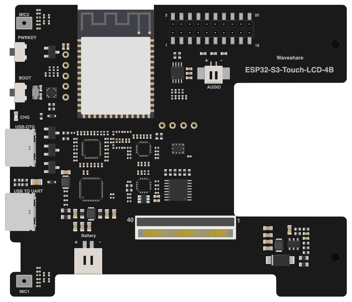
Board illustration
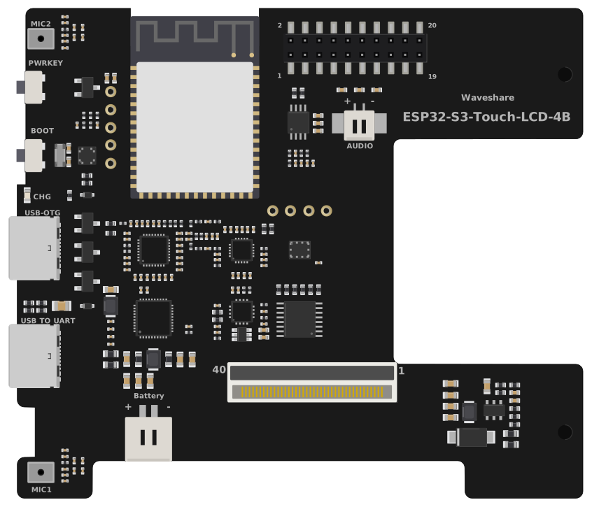
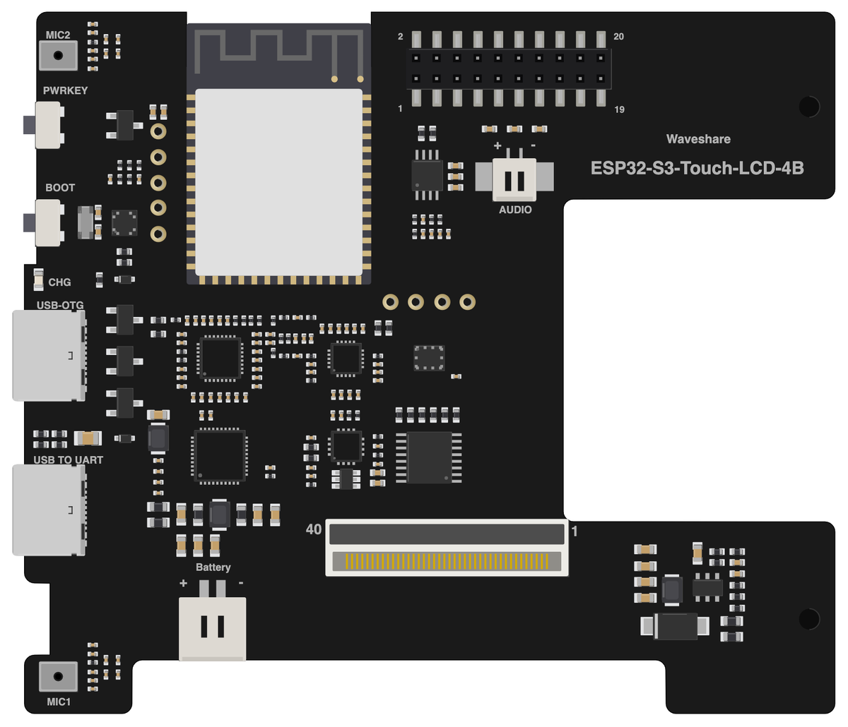
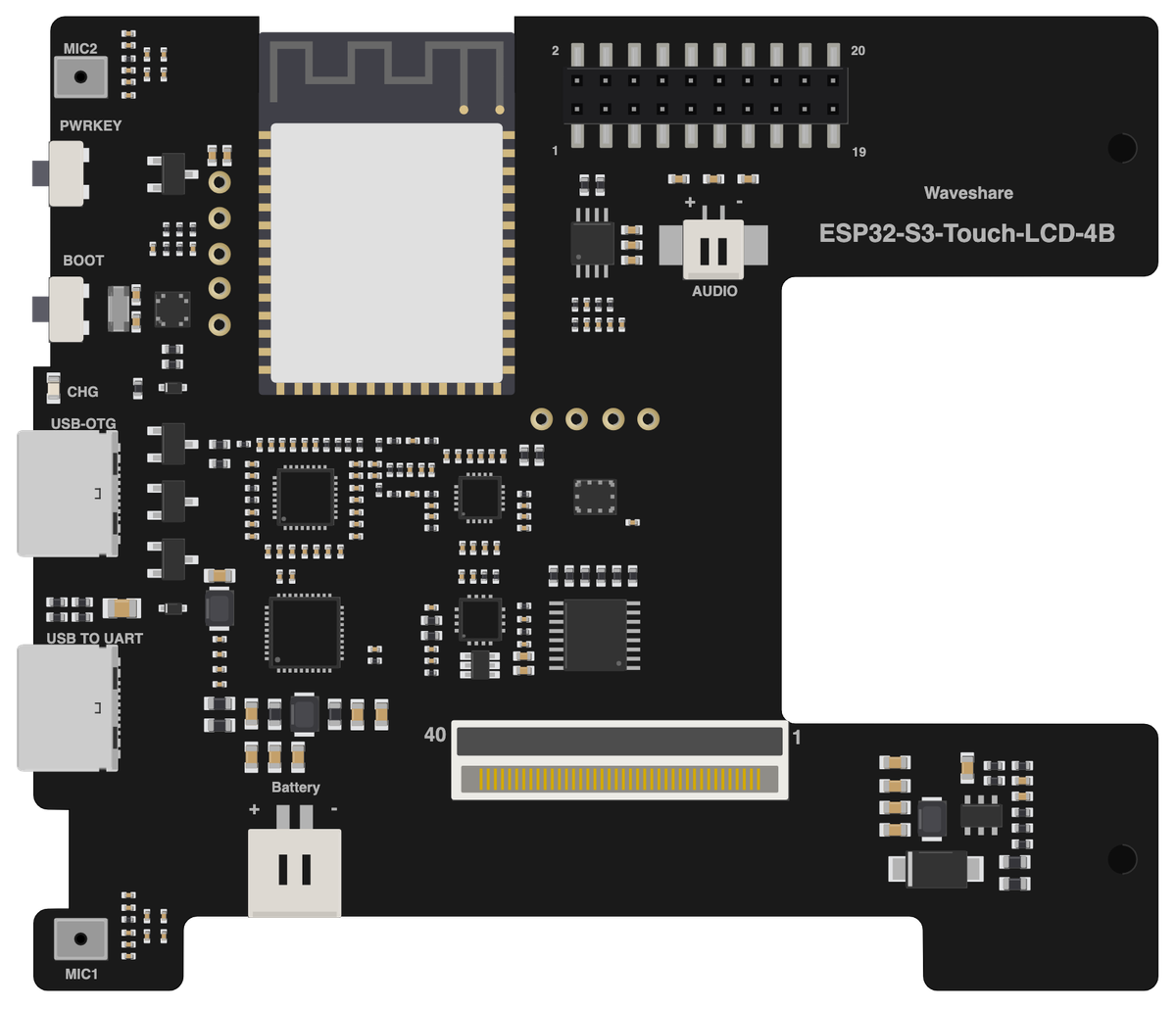
The bare Waveshare ESP32-S3-Touch-LCD-4B board drawn to scale at 86.5 × 86.5 mm, with no pin labels on it. Made for slide decks, wiring diagrams and project write-ups where a photo is too busy. Take the scalable SVG for print or editing, the high-resolution PNG to drop straight in, or the transparent PNG when you need it with no background behind it.
Pinout diagram
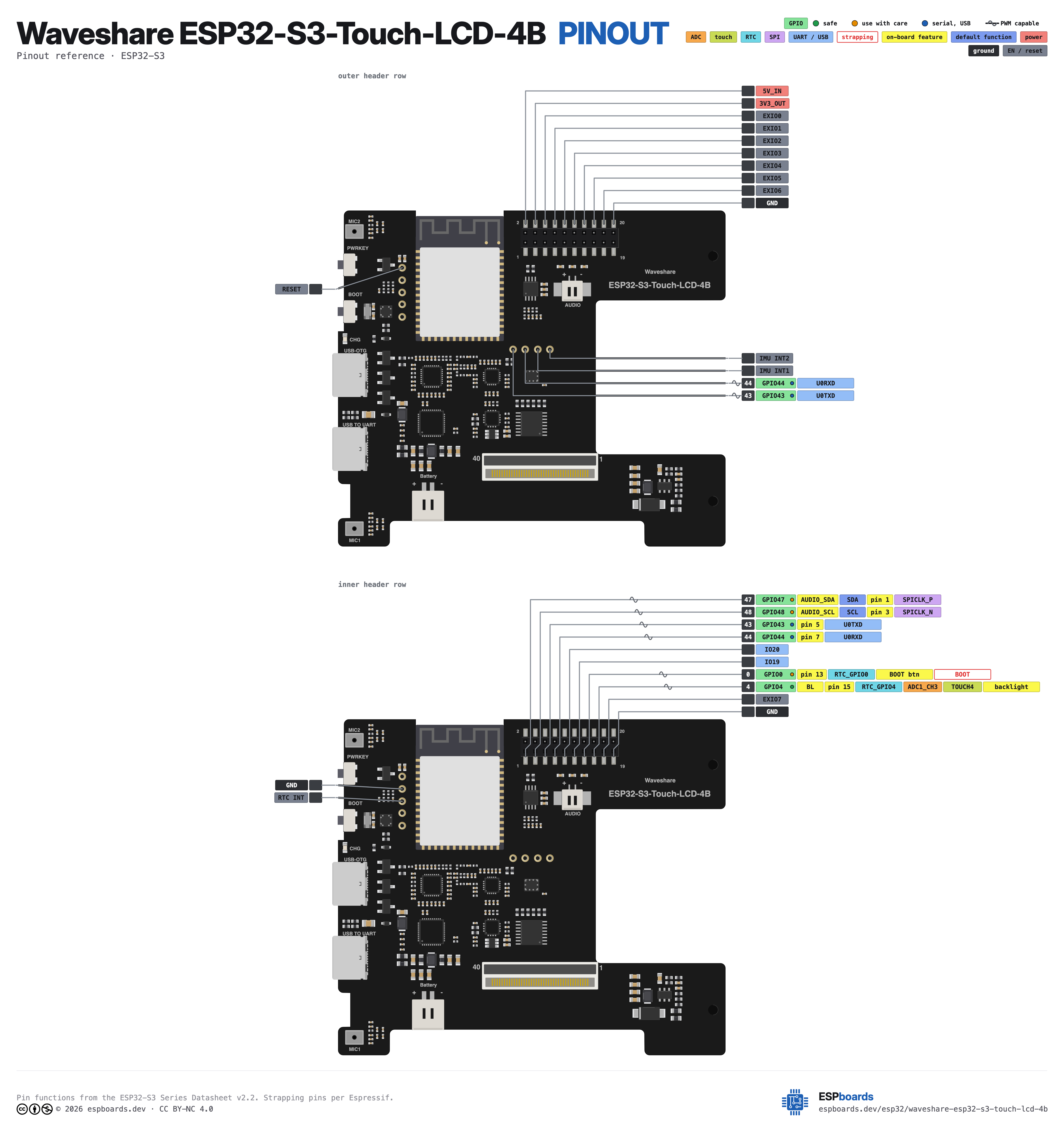
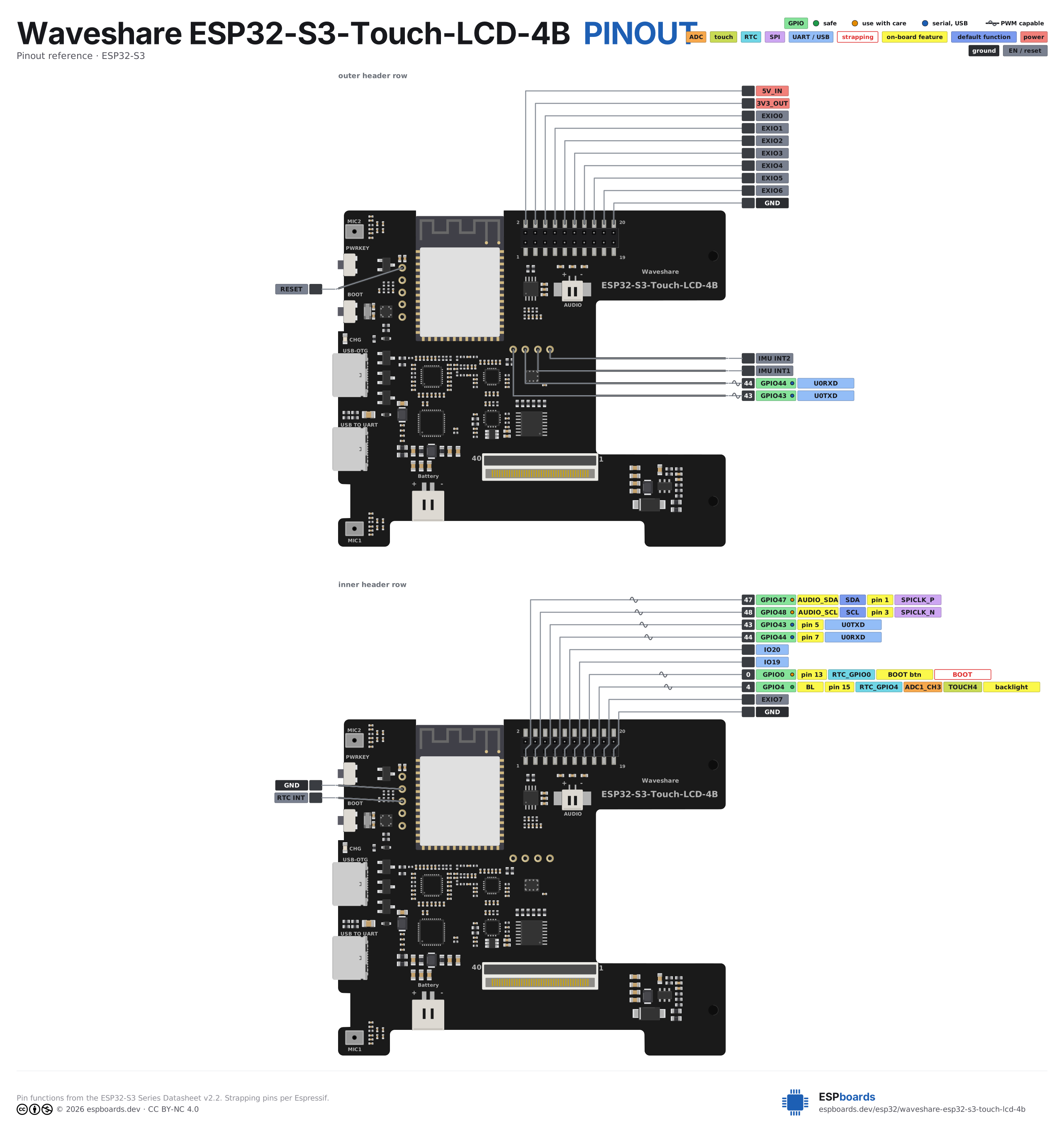
Every pin on both sides of the board with its functions, drawn by ESPboards from the ESP32-S3 Series Datasheet v2.2 - the same sheet shown at the top of this page. The PNG is a high-resolution image for screens, the SVG is vector so it stays sharp at any size, and the PDF is laid out to print on A4 or Letter.
Yours to use, share and adapt for non-commercial work, as long as you credit espboards.dev - the full terms and ready-made credit lines are here.
Specifications
ESP32-S3 · 86.5 × 86.5 mm · vs other ESP32 chips →Dimensions
About this board
At its core is the ESP32-S3 - a dual-core Xtensa with vector extensions suited to AI workloads.
Expect to pay about $33.99 - above the ~$29 typical for ESP32-S3 boards.
Only 6 GPIO are left for your own hardware - the display and onboard peripherals claim the rest.
Onboard you'll find 8MB (OPI) PSRAM, an IPS LCD 4" 480x480 display with touch, a microphone (Dual SMD microphone), a speaker connector (MX1.25 2P), an audio codec (ES8311), an amplifier (NS4150B), a QMI8658 IMU, a PCF85063 RTC, battery charging (AXP2101) via PH2.0, status LEDs (CHG) and PWRKEY/BOOT buttons.
The Waveshare ESP32-S3-Touch-LCD-4B is a 4-inch 480x480 IPS touch panel sold as a cased 86-type wall-box smart panel (86.5 x 86.5 x 14 mm), so it is a finished control panel rather than a breadboard board. It runs an ESP32-S3 N16R8 with 16 MB flash and 8 MB octal PSRAM, and the display is an ST7701 RGB panel with a GT911 capacitive touch controller.
Around the screen Waveshare fits the parts a home-control or voice panel needs: an ES8311 codec with an NS4150B speaker amplifier on an MX1.25 connector, two onboard microphones fed through an ES7210 echo-cancellation ADC, a QMI8658 IMU, a PCF85063 RTC and an AXP2101 PMIC that charges a battery on a PH2.0 connector. There are two USB-C ports, one through a CH343P bridge for flashing and one on the S3's native USB, and either one powers the board.
The trade-off is expansion. The RGB panel, I2S, I2C, UART0 and USB use every ESP32-S3 GPIO, so the 20-pin 2.0 mm header only exposes existing buses and the eight TCA9554 expander lines, each of which already has an onboard duty. It suits people who want a wall panel for ESPHome or an LVGL interface and can live with I2C and UART as the only ways to add hardware.
- ESP32-S3 N16R8 - 16 MB flash and 8 MB octal PSRAM
- ES7210 echo-cancellation ADC feeding the two onboard mics
- TCA9554PWR I2C IO expander, all eight lines routed to the 2.0 mm header
- Two USB-C ports - USB TO UART through a CH343P for flashing, USB-OTG on the S3 native USB
- PWRKEY wired to the AXP2101 PWRON input for hard power off and on
- Backlight PWM on GPIO4 into an AP3032 LED boost driver
- Sold as a cased 86-type wall-box panel, 86.5 x 86.5 x 14 mm
FAQ
5 common questionsWhich USB-C port do I flash the ESP32-S3-Touch-LCD-4B through?›
Does the ESP32-S3-Touch-LCD-4B have any free GPIOs?›
Why does touch have to be polled on this board?›
What Arduino IDE settings does it need?›
Which I2C addresses are already in use?›
Where to buy
prices are typical street pricesResources
Similar boards

