
XIAO ESP32S3 Sense
XIAO ESP32S3 with a snap-on expansion board adding an OV3660 camera, a PDM microphone and a microSD slot for vision and voice projects.

Pinout
14 pins · 2.54 mm pitch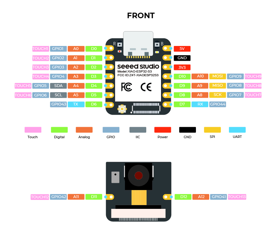
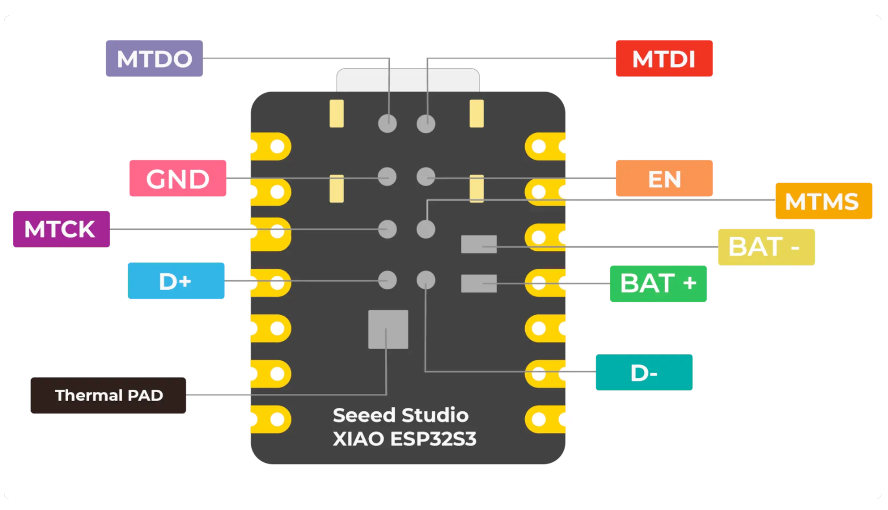
| Pin | GPIO | Labels | Status | Capabilities | Notes |
|---|---|---|---|---|---|
| 1 | 1 | D0A0GPIO1 | safe | adc · touch · pwm | |
| 2 | 2 | D1A1GPIO2 | safe | adc · touch · pwm | |
| 3 | 3 | D2A2GPIO3 | strapping | adc · touch · pwm | |
| 4 | 4 | D3A3GPIO4 | safe | adc · touch · pwm | |
| 5 | 5 | D4A4SDAGPIO5 | safe | adc · touch · pwm · i2c | |
| 6 | 6 | D5A5SCLGPIO6 | safe | adc · touch · pwm · i2c | |
| 7 | 43 | D6TXGPIO43 | strapping | uart · pwm | |
| 8 | - | 5V | power | - | 5V power input/output |
| 9 | - | GND | ground | - | |
| 10 | - | 3V3 | power | - | 3.3V power |
| 11 | 9 | D10A10MOSIGPIO9 | strapping | adc · touch · pwm · spi | |
| 12 | 8 | D9A9MISOGPIO8 | safe | adc · touch · pwm · spi | |
| 13 | 7 | D8A8SCKGPIO7 | safe | adc · touch · pwm · spi | |
| 14 | 44 | D7RXGPIO44 | strapping | uart · pwm |
Start with these
7 pins with no boot or system involvementFreely assignable - no strapping, flash, USB or JTAG duties. Ideal first picks for buttons, sensors and LEDs.
Fine - with a little care
sampled at boot or shared with debug/serial| Pin | Label | What to know | Role |
|---|---|---|---|
| D2 | GPIO3 | Sampled at reset to select JTAG interface (USB Serial/JTAG controller vs. external pins). Improper use can disable external JTAG or alter debug interface. | Strapping |
| D6 | U0TXD (GPIO43) | Used for bootloader output and UART console logs. If repurposed, you will lose the default serial output (and programming via UART0). | Other |
| D10 | FSPIHD | IO MUX pin of the general-purpose SPI2 (FSPI) bus, not of the in-package flash - that sits on GPIO26-32. The datasheet lists it as a priority-2 pin ("can be freely used without restrictions"), so it is only taken if your board wires flash, an SD card or a display to FSPI. | Other |
| D7 | U0RXD (GPIO44) | Used for bootloader input (download mode via serial). If repurposed, you cannot use the default UART0 download mode for programming the chip. | Other |
Pinout notes Across 14 pins (2.54 mm pitch), the XIAO ESP32S3 Sense exposes 11 GPIO plus 5V, GND and 3V3 for power. For peripherals, I²C is mapped to SDA on GPIO5 and SCL…
Across 14 pins (2.54 mm pitch), the XIAO ESP32S3 Sense exposes 11 GPIO plus 5V, GND and 3V3 for power.
For peripherals, I²C is mapped to SDA on GPIO5 and SCL on GPIO6; the SPI bus (MOSI, MISO, SCK) is broken out in full; TX/RX on GPIO43 and GPIO44 cover serial logging and flashing.
On the analog side there are 9 ADC-capable pins for sensors and battery monitoring, PWM on every GPIO and 9 capacitive-touch inputs.
If you want zero surprises, D0, D1, D3, D4 and 3 more are free of any such role - the safest first picks. 4 of the exposed pins carry boot-time or system duties on the ESP32-S3 (D2, D6, D10 and 1 more).
Getting started
flash your first firmware in ~2 minutesBoard: XIAO_ESP32S3 USB CDC On Boot: Enabled Flash Size: 8MB (64Mb) Flash Mode: DIO PSRAM: OPI PSRAM Partition Scheme: Default with spiffs (3MB APP/1.5MB SPIFFS) Upload Speed: 921600
// blink the onboard user LED
void setup() {
  pinMode(21, OUTPUT);
}
void loop() {
  digitalWrite(21, HIGH); delay(500);
  digitalWrite(21, LOW);  delay(500);
}[env:xiao-esp32s3-sense]
platform = espressif32
board = seeed_xiao_esp32s3
framework = arduino
monitor_speed = 115200
upload_speed = 921600
board_build.arduino.memory_type = qio_opi
build_flags = -DBOARD_HAS_PSRAMseeed_xiao_esp32s3 - or type it after board =.esp32:
board: seeed_xiao_esp32s3
variant: esp32s3
framework:
type: esp-idf
psram:
mode: octal
speed: 80MHz
# blink - GPIO21
output:
- platform: gpio
pin: 21
id: led_out
light:
- platform: binary
name: "LED"
output: led_outseeed_xiao_esp32s3 (same ids as PlatformIO).esptool.py --chip esp32s3 --port /dev/ttyACM0 \
--baud 921600 write_flash 0x0 firmware.bin--port = your /dev/tty* (macOS/Linux) or COMx (Windows).Good to know
board-specific quirks worth 60 seconds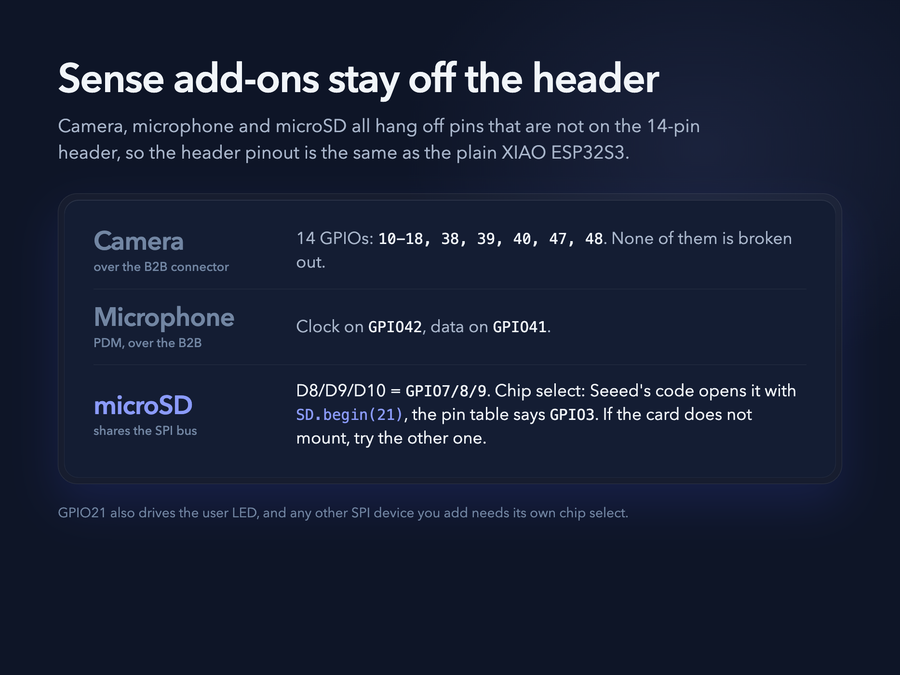
Almost nothing the expansion board adds lands on the 14-pin header. Seeed's wiki documents that the camera "occupies 14 GPIOs of the ESP32-S3" - GPIO10 to GPIO18 plus GPIO38, GPIO39, GPIO40, GPIO47 and GPIO48 - and none of those are broken out, so the header pinout is identical to the plain XIAO ESP32S3. The PDM microphone sits on GPIO42 (clock) and GPIO41 (data), which reach the expansion board over the B2B…
Almost nothing the expansion board adds lands on the 14-pin header. Seeed's wiki documents that the camera "occupies 14 GPIOs of the ESP32-S3" - GPIO10 to GPIO18 plus GPIO38, GPIO39, GPIO40, GPIO47 and GPIO48 - and none of those are broken out, so the header pinout is identical to the plain XIAO ESP32S3. The PDM microphone sits on GPIO42 (clock) and GPIO41 (data), which reach the expansion board over the B2B connector rather than the header.
The microSD slot shares the board's SPI bus (D8 SCK, D9 MISO, D10 MOSI = GPIO7/8/9) and Seeed's own examples open it with SD.begin(21), i.e. chip select on GPIO21 (the pin that also drives the user LED). Seeed's pin table lists the SD chip select as GPIO3 instead - if the card does not mount, try the other one. Any other SPI device you add needs its own chip-select pin.
To find out which sensor is fitted, Seeed's camera sketch reads it back at runtime with esp_camera_sensor_get() and compares s->id.PID against OV3660_PID. In the ESP32 camera driver's sensor.h those constants are OV3660_PID = 0x3660 and OV2640_PID = 0x26.
Seeed's Round Display has its own microSD slot on the same bus: use chip select 21 for the Sense slot and D2 for the display's slot. The J3 pads on the Sense expansion board disconnect the Sense slot if you need to. Seeed's camera tutorial adds a caveat: the Sense's pull-up resistors R4-R6 and the display's own pull-ups can stop the card from reading when both slots are fitted - cutting J3 is its fix.
Specifications
ESP32-S3 · 21 × 17.8 mm · vs other ESP32 chips →About this board
At 21 × 17.8 mm it's among the smallest boards in the whole ESP32 family.
At its core is the ESP32-S3 - a dual-core Xtensa with vector extensions suited to AI workloads.
Expect to pay about $13.90 - less than the ~$29 most ESP32-S3 boards go for.
Only 11 GPIO are left for your own hardware - the camera interface claims most of the pins.
Onboard you'll find 8MB (OPI) PSRAM, an OV3660 camera (2048x1536), a microSD slot, a microphone (PDM), battery charging via Solder pads, status LEDs (User, Charge) and Reset/Boot buttons.
It flashes over native USB - no serial-converter driver needed, which isn't a given among ESP32-S3 boards.
The XIAO ESP32S3 Sense is the XIAO ESP32S3 plus a snap-on expansion board that adds a camera, a digital microphone and a microSD slot. The same ESP32-S3R8 with 8 MB PSRAM and 8 MB flash sits underneath, so the 21 x 17.8 mm footprint is unchanged and the board only grows in height - Seeed lists it as 21 x 17.8 x 15 mm with the expansion board fitted. Wireless is unchanged too: a U.FL connector takes the rod antenna that ships in the box, and Seeed's wiki tells you to "take out the antenna inside the package and install it on the connector" for a better Wi-Fi and Bluetooth signal.
Current units ship an OV3660 (3 MP, 2048 x 1536). Seeed's wiki states that the OV2640 (2 MP, 1600 x 1200) used by early boards "has been discontinued, and the subsequent XIAO ESP32-S3 Sense uses the OV3660 camera model", and that the wiki's camera example code still applies to both. The microSD slot takes cards up to 32 GB, formatted FAT32.
Power comes from USB-C at 5 V or a 3.7 V lithium cell on the solder pads, and the expansion board is not free: Seeed rates the Sense at 110 mA Wi-Fi active and 3 mA in deep sleep, against 100 mA and 14 µA for the bare XIAO ESP32S3. Programming runs over the S3's native USB, and arduino-esp32 lists the board as XIAO_ESP32S3 - there is no separate Sense entry - with Tools → PSRAM → "OPI PSRAM" required before the camera works. Seeed also sells a pre-soldered variant.
- Dual-core Xtensa LX7 at up to 240 MHz
- Detachable expansion board carrying a camera, a digital microphone and a microSD slot
- Camera on the detachable expansion board is an OV3660 (3 MP, 2048x1536); early units shipped an OV2640 (2 MP, 1600x1200) before it was discontinued
- Onboard microSD slot for cards up to 32 GB, formatted FAT32
- Supports WiFi 4 (802.11 b/g/n), Bluetooth 5.0 LE and Bluetooth Mesh
- Ultra-small size (21 x 17.8 x 15 mm with the expansion board fitted)
Where to buy
prices are typical street pricesResources
Similar boards

