
DS18B20 Dallas Temperature Sensor
The DS18B20 is a digital temperature sensor widely used in microcontroller-based applications. It communicates via the <strong>1-Wire protocol</strong>, requiring only one data line (and ground) for communication. This sensor is known for its high accuracy, durability, and versatility, making it ideal for temperature measurement projects.

DS18B20 pinout
The DS18B20 pinout includes three pins: GND (ground), DQ (1-Wire data line), and VDD (power supply). The sensor can operate in normal mode or parasite power mode.
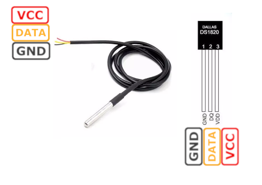
| Pin | Type | Description | Notes |
|---|---|---|---|
| Pin 1 (GND) | Ground | Ground connection | Connect to circuit ground |
| Pin 2 (DQ) | 1-Wire Data | 1-Wire data line and optional parasite power | Requires 4.7kΩ pull-up resistor to VDD |
| Pin 3 (VDD) | Power | Power supply (3.0V to 5.5V) | In parasite mode, connect to GND |
Temperature range: -55°C to +125°C
Accuracy: ±0.5°C from -10°C to +85°C
Configurable resolution: 9-bit to 12-bit (0.5°C to 0.0625°C)
Unique 64-bit address allows multiple sensors on one bus
Conversion time: 750ms at 12-bit resolution
Available in TO-92, SO-8, and waterproof probe packages
Parasite power mode requires only 2 wires (DQ + GND)
Wiring the DS18B20 to ESP32
Connect the DS18B20 to your ESP32 via the 1-Wire protocol. A 4.7kΩ pull-up resistor is required between the DQ data line and VDD (3.3V or 5V). Multiple DS18B20 sensors can share the same data line.
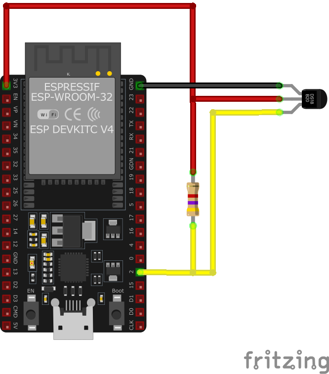
| DS18B20 pin | ESP32 pin | Purpose |
|---|---|---|
| Pin 1 (GND) | GND | Ground connection |
| Pin 2 (DQ) | GPIO4 | 1-Wire data line (with 4.7kΩ pull-up) |
| Pin 3 (VDD) | 3.3V | Power supply (or GND for parasite mode) |
CRITICAL: Add a 4.7kΩ pull-up resistor between DQ and VDD
Can use 3.3V or 5V power supply (ESP32 is 3.3V)
Multiple DS18B20 sensors can share the same DQ line
Each sensor has a unique 64-bit ROM address
For parasite power mode: connect VDD to GND, pull-up to 3.3V/5V
Waterproof probe versions available for liquid temperature measurement
Recommended wire length: up to 100 meters with proper cabling
Use DallasTemperature library for Arduino/ESP32
DS18B20 code examples
#include <OneWire.h>
#include <DallasTemperature.h>

// Data wire is connected to GPIO4 (D2 on many boards)
#define ONE_WIRE_BUS 4

// Setup a oneWire instance to communicate with any OneWire devices
OneWire oneWire(ONE_WIRE_BUS);

// Pass our oneWire reference to Dallas Temperature sensor library
DallasTemperature sensors(&oneWire);

void setup() {
  Serial.begin(115200);
  Serial.println("DS18B20 Temperature Sensor");

  // Start the DS18B20 sensor
  sensors.begin();
}

void loop() {
  // Request temperature readings from the sensor
  sensors.requestTemperatures();

  // Fetch and print the temperature
  float temperatureC = sensors.getTempCByIndex(0);
  Serial.print("Temperature: ");
  Serial.print(temperatureC);
  Serial.println("°C");

  // Delay for 2 seconds before taking the next reading
  delay(2000);
}
This Arduino sketch interfaces with the DS18B20 temperature sensor using the OneWire protocol. It reads temperature data and prints it to the Serial Monitor.
Library Requirement
To use this code, install the required libraries:
OneWire Library
- Allows communication with OneWire devices.
- Install via Arduino Library Manager or manually from:
OneWire Library
DallasTemperature Library
- Simplifies interaction with DS18B20 sensors.
- Install via Arduino Library Manager or from:
DallasTemperature Library
Code Breakdown
Setup OneWire Communication
ONE_WIRE_BUS (GPIO4)defines the data pin for DS18B20.- The
OneWireinstance is passed toDallasTemperature.
Initialization (
setup())- Serial communication starts at 115200 baud.
sensors.begin()initializes the DS18B20 sensor.
Temperature Reading (
loop())sensors.requestTemperatures()fetches sensor data.sensors.getTempCByIndex(0)retrieves the temperature in Celsius.- The value is printed to the Serial Monitor.
A 2-second delay ensures stable readings.
// Requires the official Espressif 1-Wire and DS18B20 drivers from the ESP Component Registry:
//   idf.py add-dependency "espressif/ds18b20^0.4.0"
//   idf.py add-dependency "espressif/onewire_bus^1.1.1"

#include <stdio.h>
#include <string.h>
#include "esp_log.h"
#include "esp_err.h"
#include "ds18b20.h"
#include "onewire_bus.h"
#include "freertos/FreeRTOS.h"
#include "freertos/task.h"

#define ONE_WIRE_GPIO    4   // Change this to your preferred GPIO pin
#define MAX_DS18B20      2   // Maximum number of DS18B20 sensors
#define DS18B20_CONVERSION_DELAY_MS 750  // Default conversion delay for 12-bit resolution

static const char *TAG = "DS18B20";

void app_main(void) {
    // Install the 1-Wire bus
    onewire_bus_handle_t bus = NULL;
    onewire_bus_config_t bus_config = {
        .bus_gpio_num = ONE_WIRE_GPIO,
    };

    onewire_bus_rmt_config_t rmt_config = {
        .max_rx_bytes = 10, // 1-byte ROM command + 8 bytes ROM number + 1 byte device command
    };

    ESP_ERROR_CHECK(onewire_new_bus_rmt(&bus_config, &rmt_config, &bus));

    int ds18b20_device_num = 0;
    ds18b20_device_handle_t ds18b20s[MAX_DS18B20];
    onewire_device_iter_handle_t iter = NULL;
    onewire_device_t next_onewire_device;
    esp_err_t search_result = ESP_OK;

    // Create 1-Wire device iterator to search for sensors
    ESP_ERROR_CHECK(onewire_new_device_iter(bus, &iter));
    ESP_LOGI(TAG, "Device iterator created, start searching...");

    do {
        search_result = onewire_device_iter_get_next(iter, &next_onewire_device);
        if (search_result == ESP_OK) {
            ds18b20_config_t ds_cfg = {};  // Initialize DS18B20 config

            // Check if the device is a DS18B20 sensor
            if (ds18b20_new_device_from_enumeration(&next_onewire_device, &ds_cfg, &ds18b20s[ds18b20_device_num]) == ESP_OK) {
                ESP_LOGI(TAG, "Found DS18B20[%d], address: %016llX", ds18b20_device_num, next_onewire_device.address);
                ds18b20_device_num++;
            } else {
                ESP_LOGW(TAG, "Found unknown device, address: %016llX", next_onewire_device.address);
            }
        }
    } while (search_result != ESP_ERR_NOT_FOUND);

    ESP_ERROR_CHECK(onewire_del_device_iter(iter));
    ESP_LOGI(TAG, "Searching done, %d DS18B20 device(s) found", ds18b20_device_num);

    // Read and print temperature from each detected DS18B20 sensor
    while (1) {
        for (int i = 0; i < ds18b20_device_num; i++) {
            float temperature = 0.0;
            if (ds18b20_trigger_temperature_conversion(ds18b20s[i]) == ESP_OK) {
                vTaskDelay(pdMS_TO_TICKS(DS18B20_CONVERSION_DELAY_MS));  // Wait for conversion
                if (ds18b20_get_temperature(ds18b20s[i], &temperature) == ESP_OK) {
                    ESP_LOGI(TAG, "DS18B20[%d] Temperature: %.2f°C", i, temperature);
                } else {
                    ESP_LOGE(TAG, "Failed to get temperature from DS18B20[%d]", i);
                }
            } else {
                ESP_LOGE(TAG, "Failed to trigger temperature conversion for DS18B20[%d]", i);
            }
        }
        vTaskDelay(pdMS_TO_TICKS(2000));  // Wait 2 seconds before the next reading
    }
}
ESP-IDF ships no DS18B20 driver of its own, so this example uses Espressif's official ds18b20 and onewire_bus components from the ESP Component Registry. Install it into your project first with idf.py add-dependency "espressif/ds18b20^0.4.0" and idf.py add-dependency "espressif/onewire_bus^1.1.1", then build as usual.
The 1-Wire bus is driven by the RMT peripheral for reliable timing. The code enumerates the bus with a device iterator, registers every DS18B20 it finds (up to MAX_DS18B20), then repeatedly triggers a conversion on each sensor, waits the 750 ms a 12-bit conversion needs, and reads the temperature. Multiple sensors can share the same data line - that is the DS18B20's main party trick.
one_wire:
  - platform: gpio
    pin: GPIO4

sensor:
  - platform: dallas_temp
    # With multiple sensors on the bus, add their address (logged at boot)
    name: "DS18B20 Temperature"
    update_interval: 60s
Since ESPHome 2024.2 the 1-Wire bus is configured with the one_wire component, and each DS18B20 becomes a dallas_temp sensor. With a single sensor on the bus no address is needed; with several, ESPHome logs each sensor's address at boot so you can pin them down. Data line on GPIO4 with a 4.7k pull-up, per the wiring above.
[env:esp32dev]
platform = espressif32
board = esp32dev
framework = arduino
monitor_speed = 115200
lib_deps =
    paulstoffregen/OneWire @ ^2.3.8
milesburton/DallasTemperature @ ^4.0.4#include <Arduino.h>
#include <OneWire.h>
#include <DallasTemperature.h>
// Data wire is connected to GPIO4 (D2 on many boards)
#define ONE_WIRE_BUS 4
// Setup a oneWire instance to communicate with any OneWire devices
OneWire oneWire(ONE_WIRE_BUS);
// Pass our oneWire reference to Dallas Temperature sensor library
DallasTemperature sensors(&oneWire);
void setup() {
Serial.begin(115200);
Serial.println("DS18B20 Temperature Sensor");
// Start the DS18B20 sensor
sensors.begin();
}
void loop() {
// Request temperature readings from the sensor
sensors.requestTemperatures();
// Fetch and print the temperature
float temperatureC = sensors.getTempCByIndex(0);
Serial.print("Temperature: ");
Serial.print(temperatureC);
Serial.println("°C");
// Delay for 2 seconds before taking the next reading
delay(2000);
}#includeand#includeimport the required libraries for 1-Wire communication and DS18B20 sensor handling.#define ONE_WIRE_BUS 4sets the GPIO pin connected to the DS18B20 data pin.- The
setup()function initializes serial communication and the DS18B20 sensor withsensors.begin(). - In the
loop()function,sensors.requestTemperatures()requests a temperature measurement. sensors.getTempCByIndex(0)retrieves the temperature in Celsius, which is printed to the serial monitor usingSerial.print().
import machine
import onewire
import ds18x20
import time

# Define the GPIO pin where the DS18B20 data line is connected
ds_pin = machine.Pin(4)

# Create a OneWire object
ow = onewire.OneWire(ds_pin)

# Create a DS18X20 object
ds = ds18x20.DS18X20(ow)

# Scan for DS18B20 devices on the bus
roms = ds.scan()
print("Found DS18B20 devices:", roms)

while True:
    # Request temperature conversion
    ds.convert_temp()
    time.sleep(1)  # Wait for the conversion to complete

    # Read temperature from each device
    for rom in roms:
        temp = ds.read_temp(rom)
        print("Temperature:", temp, "°C")

    time.sleep(2)  # Delay before the next reading
import machine,import onewire, andimport ds18x20are used to handle GPIO pins, 1-Wire protocol, and DS18B20 sensor operations respectively.ds_pin = machine.Pin(4)sets GPIO4 as the pin connected to the DS18B20 data line.- The
OneWireandDS18X20objects are initialized to communicate with the sensor. ds.scan()searches for DS18B20 sensors connected to the bus and returns their ROM addresses.- Inside a loop,
ds.convert_temp()starts a temperature measurement, andds.read_temp(rom)reads the temperature from each sensor. - The temperature readings are printed to the console with
print().
DS18B20 specifications
About the DS18B20
The DS18B20 is a Dallas/Maxim (now Analog Devices) 1-Wire digital thermometer - temperature only, no humidity - built around a clever trick: every chip carries a unique 64-bit ROM address, so dozens of them can share a single GPIO pin and pull-up resistor with no address conflicts. Accuracy is ±0.5 degC across a -10 to +85 degC band, with the full measurable range stretching to -55 to +125 degC, and resolution is configurable from 9 to 12 bits. It can also run in “parasite power” mode, stealing power from the data line itself so wiring drops to two wires instead of three.
One thing worth knowing before buying a bag of them: a widely cited reverse-engineering project that bought 1,000 sensors from 70 sellers found that most DS18B20s sold outside authorized distributors are counterfeit clones, with measurable differences from the genuine part - some fail to support parasite power properly, read with a bigger-than-spec offset, or are missing the internal EEPROM entirely. For a hobby weather station this rarely matters, but if you see flaky parasite-mode behavior or an offset that won’t calibrate away, a clone chip is a documented and common cause worth ruling out.
The classic use case is the waterproof stainless-probe version on a cable, popular for pool, soil, or outdoor temperature since it costs little more than the bare TO-92 package. If a project also needs humidity, pair it with a DHT22, or move to an I2C part like the SHT40 that measures both in one package. We cover the DS18B20 alongside its rivals in the ESP32 temperature sensor guide.
DS18B20 troubleshooting
One wire DS18B20 reading +85°C
›
Issue: The DS18B20 sensor always starts with a default reading of 85°C when it powers on. This happens because it hasn't measured the actual temperature yet, or the temperature conversion has not been completed.
How to Fix It:
- Ensure that your code calls
sensors.requestTemperatures()to initiate a temperature conversion - Wait for the sensor to complete the conversion. For the highest accuracy (12-bit resolution), this requires a delay of 750 milliseconds. Use
delay(750);after the command. - After the delay, read the temperature using
sensors.getTempCByIndex(0);. The value will now reflect the actual temperature.
DS18B20 Reading of -127°C
›
Issue: The sensor returns a reading of -127°C, which indicates a communication failure or that the sensor is not detected. This may be caused by wiring issues, an incorrect pull-up resistor value, or a faulty sensor. However, this error could also occur intermittently due to transient issues during communication.
Possible Causes:
- Wiring problems, such as loose or incorrect connections.
- Missing or incorrectly sized pull-up resistor (4.7kΩ is standard).
- Insufficient power supply or grounding issues.
- Sensor damage or faulty hardware.
- Improper GPIO configuration in the code.
Solution:
- Check the sensor's wiring and ensure all connections are secure.
- Ensure a 4.7kΩ pull-up resistor is installed between the data line and VCC (adjust to 3.3kΩ if using 3.3V logic).
- Test the power supply to confirm it falls within the sensor's operating range (3.0V to 5.5V).
- Replace the sensor if hardware issues are suspected.
- Use error handling in your code to retry reading the sensor if a -127°C value is detected
Where to buy the DS18B20

Resources
Similar sensors


