
KY-005 Infrared Transmitter Module
The KY-005 is an infrared transmitter module that emits infrared light at a wavelength of 940 nm. It is commonly used in remote control applications and can be paired with the KY-022 Infrared Receiver Module for infrared communication projects.

KY-005 pinout
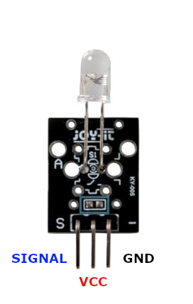
The KY-005 is a 3-pin infrared LED transmitter module (940 nm):
| Pin | Type | Description | Notes |
|---|---|---|---|
| Pin (S) | Communication | Signal/control pin | Connects to GPIO for IR transmission |
| Pin (middle) | Power | Optional ground | Use if external resistor is soldered on module |
| Pin (-) | Power | Ground connection | Requires series resistor (120Ω@3.3V, 220Ω@5V) |
Interface: Digital output for IR LED control
Wavelength: 940 nm infrared emission
Current: 20mA forward current, 1.1V forward voltage
Resistor: 120Ω for 3.3V, 220Ω for 5V power
Pairs With: KY-022 IR Receiver for complete IR communication
Applications: Remote controls, IR data transmission, wireless communication
Wiring the KY-005 to ESP32
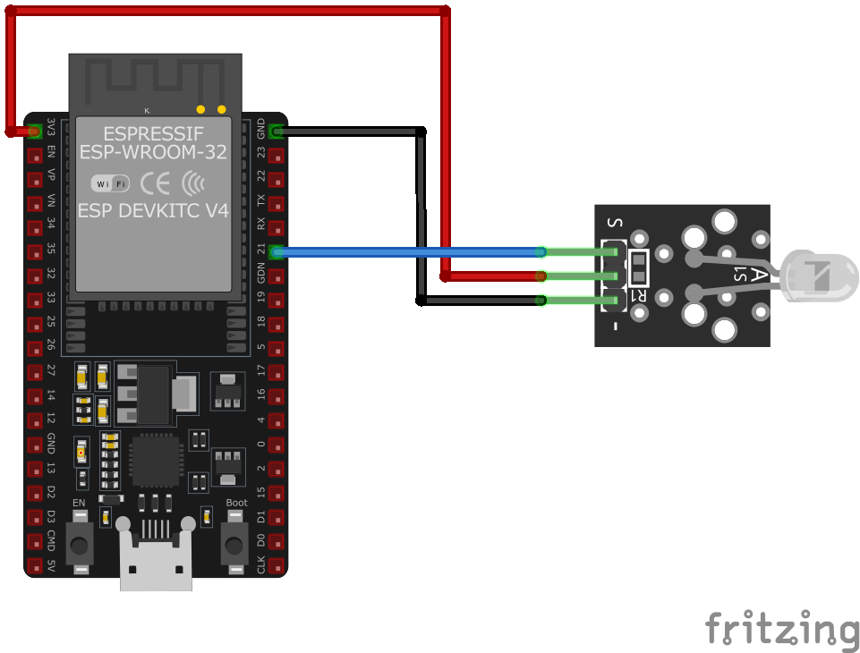
To interface the KY-005 with an ESP32 for IR transmission:
| KY-005 pin | ESP32 pin | Purpose |
|---|---|---|
| Pin (S) | GPIO17 | IR control signal (any GPIO) |
| Pin (-) | GND | Ground (via series resistor) |
| Pin (middle) | GND | Optional ground connection · optional |
Series Resistor Required: Add 120Ω resistor for 3.3V or 220Ω for 5V
GPIO Selection: Any GPIO pin works, GPIO17 is just an example
Power: Module typically powered from 3.3V via resistor to LED
Middle Pin: Only connect if external resistor is already on module
KY-005 code examples
// Requires library: "IRremote"
#include <IRremote.hpp>

#define IR_SEND_PIN 17 // KY-005 signal pin (GPIO17, matches the wiring above)

void setup() {
    Serial.begin(115200);
    IrSender.begin(IR_SEND_PIN);
    Serial.println("KY-005 Infrared Transmitter Test");
}

void loop() {
    Serial.println("Sending NEC address 0x00, command 0x2C");
    IrSender.sendNEC(0x00, 0x2C, 3); // address, command, number of repeats
    delay(5000); // Wait 5 seconds before sending again
}
The example uses version 4 of the IRremote library: IrSender.begin() attaches the transmitter to GPIO17 (matching the wiring above), and sendNEC(address, command, repeats) transmits a complete NEC frame. Pair it with a KY-022 receiver on a second board to verify transmission - the receiver should report address 0x00 and command 0x2C.
#include <stdio.h>
#include "freertos/FreeRTOS.h"
#include "freertos/task.h"
#include "driver/rmt_tx.h"
#define IR_GPIO GPIO_NUM_17 // KY-005 signal pin, matches the wiring above
#define RESOLUTION_HZ 1000000 // 1 MHz -> 1 tick = 1 us
// Build one NEC frame (leader + 32 bits + stop) as RMT symbols
static size_t build_nec_frame(uint8_t address, uint8_t command, rmt_symbol_word_t *symbols)
{
uint32_t data = ((uint32_t)(~command) << 24) | ((uint32_t)command << 16) |
((uint32_t)(~address) << 8) | address;
size_t n = 0;
symbols[n++] = (rmt_symbol_word_t){ .level0 = 1, .duration0 = 9000,
.level1 = 0, .duration1 = 4500 }; // leader
for (int i = 0; i < 32; i++) {
bool bit = (data >> i) & 1;
symbols[n++] = (rmt_symbol_word_t){ .level0 = 1, .duration0 = 560,
.level1 = 0, .duration1 = bit ? 1690 : 560 };
}
symbols[n++] = (rmt_symbol_word_t){ .level0 = 1, .duration0 = 560,
.level1 = 0, .duration1 = 0x7FFF }; // stop burst
return n;
}
void app_main(void)
{
rmt_tx_channel_config_t tx_config = {
.clk_src = RMT_CLK_SRC_DEFAULT,
.gpio_num = IR_GPIO,
.mem_block_symbols = 64,
.resolution_hz = RESOLUTION_HZ,
.trans_queue_depth = 4,
};
rmt_channel_handle_t tx_channel = NULL;
ESP_ERROR_CHECK(rmt_new_tx_channel(&tx_config, &tx_channel));
// NEC uses a 38 kHz carrier - the RMT peripheral modulates it in hardware
rmt_carrier_config_t carrier = {
.frequency_hz = 38000,
.duty_cycle = 0.33,
};
ESP_ERROR_CHECK(rmt_apply_carrier(tx_channel, &carrier));
ESP_ERROR_CHECK(rmt_enable(tx_channel));
rmt_encoder_handle_t copy_encoder = NULL;
rmt_copy_encoder_config_t encoder_config = {};
ESP_ERROR_CHECK(rmt_new_copy_encoder(&encoder_config, ©_encoder));
static rmt_symbol_word_t frame[34];
rmt_transmit_config_t transmit_config = { .loop_count = 0 };
while (1) {
size_t n = build_nec_frame(0x00, 0x2C, frame); // address, command
printf("Sending NEC address 0x00, command 0x2C\n");
ESP_ERROR_CHECK(rmt_transmit(tx_channel, copy_encoder, frame,
n * sizeof(rmt_symbol_word_t), &transmit_config));
ESP_ERROR_CHECK(rmt_tx_wait_all_done(tx_channel, pdMS_TO_TICKS(1000)));
vTaskDelay(pdMS_TO_TICKS(5000)); // send again every 5 seconds
}
}This example uses ESP-IDF's modern RMT transmit driver: the NEC frame (9 ms/4.5 ms leader, 32 bits LSB-first with address, command and their complements, and a stop burst) is built as RMT symbols with microsecond timing, and rmt_apply_carrier() makes the peripheral modulate the 38 kHz carrier in hardware - no bit-banging. Pair it with the KY-022 receiver page, whose example listens for exactly this address/command.
remote_transmitter:
  pin: GPIO17  # KY-005 signal pin, matches the wiring above
  carrier_duty_percent: 50%

button:
  - platform: template
    name: "KY-005 Send IR Signal"
    on_press:
      - remote_transmitter.transmit_nec:
          address: 0x0000
          command: 0x2C
The remote_transmitter component drives the IR LED on GPIO17 with a 50% carrier duty (right for a single LED). The template button sends an NEC frame - address 0x0000, command 0x2C - which you can receive with a KY-022 on another board (the KY-022 example listens for exactly this code).
[env:esp32]
platform = espressif32
board = esp32dev
framework = arduino
lib_deps =
z3t0/IRremote#include <Arduino.h>
#include <IRremote.h>
IRsend irsend;
void setup() {
Serial.begin(115200);
Serial.println("KY-005 Infrared Transmitter Test");
}
void loop() {
Serial.println("Sending IR signal");
irsend.sendNEC(0x00FF, 32);
delay(5000);
}This PlatformIO code initializes the KY-005 Infrared Transmitter using the IRremote library. It sends an NEC protocol signal every 5 seconds, making it suitable for testing IR communication.
import machine
import time

IR_TX_PIN = machine.Pin(17, machine.Pin.OUT)

def send_pulse():
    for _ in range(32):
        IR_TX_PIN.value(1)
        time.sleep_us(562)
        IR_TX_PIN.value(0)
        time.sleep_us(562)

while True:
    print("Sending IR signal")
    send_pulse()
    time.sleep(5)
This MicroPython script configures the KY-005 Infrared Transmitter on GPIO17. It simulates an NEC-like IR signal by toggling the pin on and off rapidly, mimicking the transmission of an infrared command.
KY-005 specifications
About the KY-005
The KY-005 is a bare 940nm IR LED on a 3-pin breakout, meant to be paired with a receiver like the KY-022 infrared receiver module for a two-way IR link. There’s no driver or protocol logic onboard, just the LED itself - Joy-IT’s datasheet lists roughly 1.1V forward voltage and 20mA forward current - plus, depending on the board revision, either a pre-soldered series resistor or bare pads where you add one yourself (120 ohm for a 3.3V supply, 220 ohm for 5V).
Because it’s a plain LED and not a modulated transmitter, sending anything a real remote-control receiver can decode - NEC, RC5, Sony SIRC, or similar - means generating the 38kHz carrier and the protocol’s on/off timing entirely in software (a library like IRremote handles this on ESP32). Driven straight from a GPIO with no carrier, it just blinks IR on and off, which confirms the LED is alive but won’t talk to a TV or an IR receiver expecting an actual protocol.
KY-005 troubleshooting
Infrared Signal Not Emitted
›
Issue: The module does not emit an infrared signal.
Solutions:
- Verify that the correct series resistor is used based on the input voltage (e.g., 220Ω for 5V).
- Ensure all connections are secure and correctly placed.
- Confirm that the microcontroller's GPIO pin is configured correctly in the code.
- Test the infrared LED with a camera to see if it lights up when active (infrared light is visible to most digital cameras).
Overheating or Damage to the Module
›
Issue: The module becomes hot or is damaged during operation.
Solutions:
- Check that the appropriate series resistor is in place to limit current through the LED.
- Ensure the input voltage does not exceed the module's specifications.
- Inspect for any short circuits or incorrect wiring that could cause excessive current draw.
Where to buy the KY-005

Resources
Similar sensors


