
KY-051 Voltage Translator / Level Shifter
The KY-051 is a versatile voltage level shifter module that enables safe communication between devices operating at different voltage levels. With four bi-directional channels, it ensures compatibility and protects components from potential damage due to voltage mismatches.

KY-051 pinout
The KY-051 is an 8-pin (4-channel) bidirectional level shifter module:
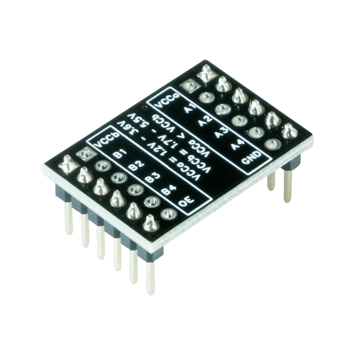
| Pin | Type | Description | Notes |
|---|---|---|---|
| VCCa | Power | Low voltage reference | 1.2V to 3.6V (e.g., 3.3V) |
| VCCb | Power | High voltage reference | 1.7V to 5.5V (e.g., 5V) |
| GND | Power | Common ground | Shared between both sides |
| A1-A4 | Communication | Low voltage side I/O | Connects to VCCa voltage device |
| B1-B4 | Communication | High voltage side I/O | Connects to VCCb voltage device |
Interface: 4-channel bidirectional level shifter
IC: TXS0108E or similar 8-channel voltage translator
Bidirectional: Signals can flow from A→B or B→A automatically
VCCa Range: 1.2V to 3.6V (low voltage side)
VCCb Range: 1.7V to 5.5V (high voltage side)
Requirement: VCCb must be ≥ VCCa
Applications: 3.3V 5V conversion, I2C/SPI/UART level shifting, sensor interfacing
Wiring the KY-051 to ESP32
To interface the KY-051 for voltage level translation:
| KY-051 pin | ESP32 pin | Purpose |
|---|---|---|
| VCCa | 3.3V | Low voltage reference (ESP32 side) |
| VCCb | 5V (from external) | High voltage reference (5V device side) |
| GND | GND | Common ground |
| A1-A4 | ESP32 GPIO pins | Connect to 3.3V device I/O |
| B1-B4 | 5V device I/O | Connect to 5V device I/O |
Bidirectional: No direction configuration needed - signals automatically translate both ways
VCCa → ESP32: Connect VCCa to ESP32 3.3V, A channels to ESP32 GPIO
VCCb → 5V Device: Connect VCCb to 5V supply, B channels to 5V device I/O
Common Ground: CRITICAL - both devices must share the same GND
I2C Compatible: Can be used for I2C level shifting (connect SCL/SDA to A/B pairs)
SPI Compatible: Works with SPI signals (MOSI, MISO, SCK, CS)
Speed: Up to 60 Mbps typical, suitable for most digital protocols
No External Components: Built-in pull-up resistors on some versions
KY-051 code examples
// The KY-051 is a passive level shifter: signals on the A side (3.3V) appear
// level-shifted on the B side (5V) and vice versa - no code is needed on the
// module itself. This sketch drives channel A1 from the ESP32 so you can
// measure the shifted 5V signal on B1.

#define SHIFTER_A1_PIN 16 // ESP32 GPIO16 -> KY-051 A1 (B1 outputs the 5V copy)

void setup() {
    pinMode(SHIFTER_A1_PIN, OUTPUT);
    Serial.begin(115200);
    Serial.println("KY-051 Voltage Translator Test - probe B1 with a multimeter");
}

void loop() {
    digitalWrite(SHIFTER_A1_PIN, HIGH); // B1 reads ~5V
    Serial.println("A1 HIGH (3.3V) -> B1 ~5V");
    delay(2000);
    digitalWrite(SHIFTER_A1_PIN, LOW); // B1 reads 0V
    Serial.println("A1 LOW (0V) -> B1 0V");
    delay(2000);
}
The KY-051 is a passive level translator - it needs no code of its own. The sketch simply toggles GPIO16, which feeds channel A1 on the module's 3.3V side; the module mirrors the signal on B1 at 5V, which you can confirm with a multimeter or logic analyzer. In real projects the module sits transparently between the ESP32 and a 5V device (both power rails and both grounds must be connected, as in the wiring above).
#include <stdio.h>
#include "freertos/FreeRTOS.h"
#include "freertos/task.h"
#include "driver/gpio.h"

#define LOW_VOLT_PIN GPIO_NUM_2  // Low voltage side (3.3V logic)
#define HIGH_VOLT_PIN GPIO_NUM_3 // High voltage side (5V logic)

void app_main() {
    gpio_reset_pin(LOW_VOLT_PIN);
    gpio_reset_pin(HIGH_VOLT_PIN);
    gpio_set_direction(LOW_VOLT_PIN, GPIO_MODE_INPUT);
    gpio_set_direction(HIGH_VOLT_PIN, GPIO_MODE_OUTPUT);
    printf("KY-051 Voltage Level Shifter Test\n");

    while (1) {
        int low_signal = gpio_get_level(LOW_VOLT_PIN);
        gpio_set_level(HIGH_VOLT_PIN, low_signal);
        printf("Low Voltage Signal: %d -> High Voltage Output: %d\n", low_signal, gpio_get_level(HIGH_VOLT_PIN));
        vTaskDelay(pdMS_TO_TICKS(500));
    }
}
This ESP-IDF code configures GPIO2 as an input (low voltage side) and GPIO3 as an output (high voltage side). It continuously reads the input signal, shifts it to the high voltage side, and prints the values to the console every 500ms.
# The KY-051 is a passive level translator - it needs no driver. This toggles
# GPIO16 into channel A1; the module mirrors it at 5V on B1.
switch:
  - platform: gpio
    pin: GPIO16
    name: "KY-051 A1 Signal (B1 mirrors at 5V)"
The KY-051 is a passive level translator - there is nothing to configure on the module itself. This minimal example toggles GPIO16 into channel A1 so you can verify the 5V copy on B1 with a meter; in real projects the module simply sits between a 3.3V ESP32 pin and a 5V device, with both supply rails and grounds connected.
[env:esp32]
platform = espressif32
board = esp32dev
framework = arduino#include <Arduino.h>
#define LOW_VOLT_PIN 2
#define HIGH_VOLT_PIN 3
void setup() {
pinMode(LOW_VOLT_PIN, INPUT);
pinMode(HIGH_VOLT_PIN, OUTPUT);
Serial.begin(115200);
Serial.println("KY-051 Voltage Level Shifter Test");
}
void loop() {
int low_signal = digitalRead(LOW_VOLT_PIN);
digitalWrite(HIGH_VOLT_PIN, low_signal);
Serial.printf("Low Voltage Signal: %d -> High Voltage Output: %d\n", low_signal, digitalRead(HIGH_VOLT_PIN));
delay(500);
}This PlatformIO code configures GPIO2 as an input and GPIO3 as an output to test the KY-051 voltage level shifter. It reads the signal from the low voltage side and shifts it to the high voltage side, printing the results to the serial monitor every 500ms.
import machine
import time

LOW_VOLT_PIN = machine.Pin(2, machine.Pin.IN)
HIGH_VOLT_PIN = machine.Pin(3, machine.Pin.OUT)

while True:
    low_signal = LOW_VOLT_PIN.value()
    HIGH_VOLT_PIN.value(low_signal)
    print("Low Voltage Signal:", low_signal, "-> High Voltage Output:", HIGH_VOLT_PIN.value())
    time.sleep(0.5)
This MicroPython script configures GPIO2 as an input and GPIO3 as an output for the KY-051 voltage level shifter. It continuously reads the low voltage signal, shifts it to the high voltage side, and prints the values every 500ms.
KY-051 specifications
About the KY-051
The KY-051 is a passive level-shifter board, typically built around a TXS0108E-family bidirectional translator: it needs no configuration and does not run any logic of its own, just two supply rails (VCCa for the low side, VCCb for the high side, with VCCb required to be equal to or above VCCa) and four channels that mirror whatever signal appears on either side onto the other. That autonomous behavior is exactly why it pairs so well with something like the KY-050, whose Echo pin outputs a 5V signal an ESP32 GPIO should not see directly - wire VCCa to 3.3V and VCCb to 5V, put the ESP32 side on the A channels and the 5V device on the B channels, and the translation just happens.
Where this chip family runs into trouble is I2C: the TXS0108E senses direction by detecting which side is pulling a line low rather than by dedicated control logic, and that scheme gets unreliable on buses with multiple devices or longer wiring, sometimes latching a line low or missing transitions. For a single device on a short wire it is fine, but a shared I2C bus with several 5V and 3.3V peripherals is better served by a dedicated I2C level shifter built around discrete MOSFETs (the common BSS138 design), which handles the open-drain, multi-master nature of I2C more predictably than a general-purpose logic translator like this one.
KY-051 troubleshooting
No Signal Translation
›
Issue: Signals are not being translated between voltage levels.
Solutions:
- Verify that
VCCbis greater than or equal toVCCaas required. - Ensure all connections are secure and correctly wired according to the pinout diagram.
- Confirm that both devices share a common ground connection.
Unstable Signal Transmission
›
Issue: Signal transmission is erratic or unreliable.
Solutions:
- Check for loose or faulty wiring connections.
- Ensure that the voltage levels supplied to
VCCaandVCCbare within the specified ranges. - Verify that the connected devices are functioning properly and are compatible with the voltage levels being used.
Resources
Similar sensors


