
Espressif ESP32-C3-AWS-ExpressLink-DevKit
ESP32-C3 dev board with AWS ExpressLink - simplifies secure cloud connectivity for IoT products.

Espressif ESP32-C3-AWS-ExpressLink-DevKit Pinout
22 pins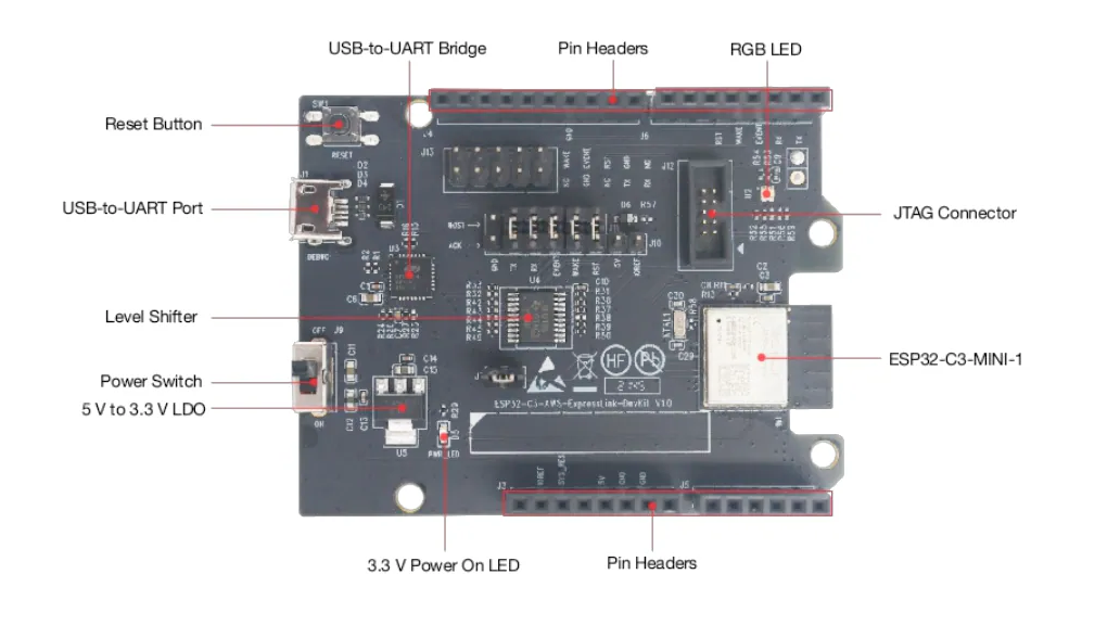
| Pin | GPIO | Labels | Status | Capabilities | Notes |
|---|---|---|---|---|---|
| 1 | 0 | A0PWM | safe | adc | |
| 2 | 1 | A1PWM | safe | adc | |
| 3 | 2 | A2PWM | strapping | adc | |
| 4 | 3 | A3PWM | safe | adc | |
| 5 | 4 | A4PWM | strapping | adc | |
| 6 | 5 | PWM | strapping | - | |
| 7 | 6 | PWM | strapping | - | |
| 8 | 7 | PWM | strapping | - | |
| 9 | 8 | PWM | strapping | - | |
| 10 | 9 | PWM | strapping | - | |
| 11 | 10 | PWM | safe | - | |
| 12 | 11 | PWM | strapping | - | |
| 13 | 12 | PWM | strapping | - | |
| 14 | 13 | PWM | strapping | - | |
| 15 | 14 | PWM | strapping | - | |
| 16 | 15 | PWM | strapping | - | |
| 17 | 16 | PWM | strapping | - | |
| 18 | 17 | PWM | strapping | - | |
| 19 | 18 | PWM | uart | - | |
| 20 | 19 | PWM | uart | - | |
| 21 | 20 | PWM | uart | - | |
| 22 | 21 | PWM | uart | - |
Start with these
4 pins with no boot or system involvementFreely assignable - no strapping, flash, USB or JTAG duties. Ideal first picks for buttons, sensors and LEDs.
Fine - with a little care
9 pins · 9 things to knowA2GPIO2 Strapping pin, but it does not select the boot mode - GPIO9 does. Espressif only recommend pulling it up against reset-time glitches. Floating by default. Strapping
A strapping pin: Espressif recommend an external pull-up against glitches at reset, so avoid heavy capacitive loads or a strong low drive here. It does not put the chip into download mode (that is GPIO9).
A4GPIO4 Bootstrapping pin; JTAG TMS; Flash data (FSPIHD in internal-flash models) JTAG
Used during boot; JTAG TMS for debugging; acts as Quad-SPI flash IO (hold data line) in internal-flash variants
PWMGPIO5 Bootstrapping pin; JTAG TDI; Flash data (FSPIWP in internal-flash models) JTAG
Used during boot; JTAG TDI for debugging; acts as Quad-SPI flash IO (write-protect data line) in internal-flash variants
PWMGPIO6 Bootstrapping pin; JTAG TCK; Flash clock (FSPICLK in internal-flash models) JTAG
Used during boot; JTAG TCK for debugging; provides flash clock in internal-flash variants
PWMGPIO7 Bootstrapping pin; JTAG TDO; Flash data (FSPID in internal-flash models) JTAG
Used during boot; JTAG TDO for debugging; acts as Quad-SPI flash IO (data line) in internal-flash variants
PWMGPIO8 Bootstrapping pin (needs HIGH at reset); also gates ROM boot message printing (UART_PRINT_CONTROL efuse) Strapping
Must be held high during reset (if low, UART flashing/boot may not work)
PWMGPIO9 Bootstrapping pin; selects boot mode (HIGH = SPI flash boot, LOW = UART download) Strapping
Controls boot mode on reset (HIGH for normal flash boot, LOW enters serial download mode)
PWMGPIO20 UART0 RXD (default serial input) UART
Used as UART0 receive (console/bootloader); repurposing may disable serial programming and debug logs
PWMGPIO21 UART0 TXD (default serial output) UART
Used as UART0 transmit (console/bootloader); repurposing may disable serial console output and printing
Only if you know the tricks
9 pins · 9 things to knowPWMGPIO11 Flash power supply pin (VDD_SPI) - can become GPIO11 if not used for flash power Flash
By default powers the SPI flash; only configurable as GPIO if the flash is powered externally (not recommended otherwise)
PWMGPIO12 Quad-SPI flash data line (HOLD# signal) Flash
Connected to flash HOLD#; not recommended for other use as it's reserved for flash communication
PWMGPIO13 Quad-SPI flash data line (WP# signal) Flash
Connected to flash WP#; not recommended for other use (used to interface with SPI flash)
PWMGPIO14 Quad-SPI flash chip select (CS#) Flash
Dedicated chip-select for SPI flash memory; cannot be repurposed for general I/O
PWMGPIO15 Quad-SPI flash clock (SCLK) Flash
Dedicated clock line for SPI flash; cannot be used as general GPIO without interfering with flash
PWMGPIO16 Quad-SPI flash data line (MISO/IO1) Flash
Used for SPI flash data transfer (data-out from flash); not available for other functions
PWMGPIO17 Quad-SPI flash data line (MOSI/IO0) Flash
Used for SPI flash data transfer (data-in to flash); not available for other functions
PWMGPIO18 USB D- line (USB Serial/JTAG interface) USB
By default connected to on-chip USB Serial/JTAG controller; to use as GPIO it must be reconfigured from its USB function
PWMGPIO19 USB D+ line (USB Serial/JTAG interface) USB
By default connected to on-chip USB Serial/JTAG controller; not available for GPIO use unless USB functionality is disabled or remapped
All 22 pins on the Espressif ESP32-C3-AWS-ExpressLink-DevKit are usable GPIO.
Beyond plain digital I/O you get 5 ADC-capable pins for sensors and battery monitoring.
9 of the exposed pins carry boot-time or system duties on the ESP32-C3 (A2, A4, PWM and 6 more) - check the guidance above before wiring anything to them. A0, A1, A3 and PWM are free of any such role - the safest first picks.
Getting started
flash your first firmware in ~2 minutesBoard: ESP32C3 Dev Module Flash Size: 4MB (32Mb) Flash Mode: DIO Partition Scheme: Default 4MB with spiffs (1.2MB APP/1.5MB SPIFFS) Upload Speed: 921600
// toggle GPIO0 - wire an LED and resistor to it
void setup() {
  pinMode(0, OUTPUT);
}
void loop() {
  digitalWrite(0, HIGH); delay(500);
  digitalWrite(0, LOW);  delay(500);
}[env:esp32-c3-aws-expresslink-devkit]
platform = espressif32
board = esp32-c3-devkitm-1
framework = arduino
monitor_speed = 115200
upload_speed = 921600esp32-c3-devkitm-1 - or type it after board =.esp32:
board: esp32-c3-devkitm-1
variant: esp32c3
framework:
type: esp-idf
# blink - GPIO0
output:
- platform: gpio
pin: 0
id: led_out
light:
- platform: binary
name: "LED"
output: led_outesp32-c3-devkitm-1 (same ids as PlatformIO).esptool.py --chip esp32c3 --port /dev/ttyACM0 \
--baud 921600 write_flash 0x0 firmware.bin--port = your /dev/tty* (macOS/Linux) or COMx (Windows).Specifications
ESP32-C3 · vs other ESP32 chips →About this board
Inside sits the ESP32-C3 - a single-core RISC-V and the budget low-power pick.
The $10.00 price tag is typical for an ESP32-C3 board.
With 22 GPIO broken out, you get more pins to play with than most ESP32-C3 boards offer.
Around the module: status LEDs (Power, RGB) and Reset buttons.
The ESP32-C3-AWS-ExpressLink-DevKit is a development board that hosts Espressif's AWS IoT ExpressLink module, based on the ESP32-C3-MINI-1-N4-A. It provides out-of-the-box, seamless AWS IoT connectivity for external host MCUs through a simple serial interface, transforming offline products into cloud-connected devices. The module handles complex tasks such as authentication, device management, connectivity, messaging, and OTA updates, relieving developers from maintaining complex firmware and providing end-to-end security and fleet management at scale.
Where to buy
prices are typical street pricesResources
Similar boards


