
XIAO ESP32C6
Tiny ESP32-C6 board by Seeed Studio with USB-C, Wi-Fi 6, BLE, and Thread - ideal for compact and wearable IoT builds.

Pinout
14 pins · 2.54 mm pitch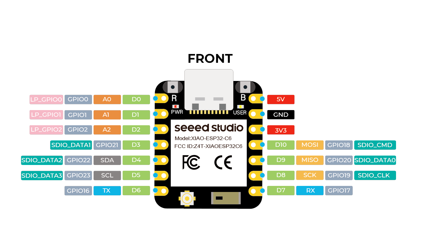
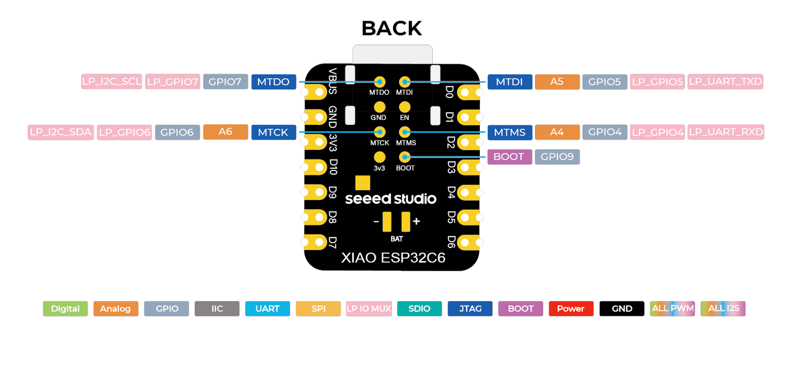
| Pin | GPIO | Labels | Status | Capabilities | Notes |
|---|---|---|---|---|---|
| 1 | 0 | D0A0GPIO0LP_GPIO0 | safe | adc · pwm | |
| 2 | 1 | D1A1GPIO1LP_GPIO1 | safe | adc · pwm | |
| 3 | 2 | D2A2GPIO2LP_GPIO2 | safe | adc · pwm | |
| 4 | 21 | D3GPIO21SDIO_DATA1 | safe | pwm | |
| 5 | 22 | D4SDAGPIO22SDIO_DATA2 | safe | i2c · pwm | |
| 6 | 23 | D5SCLGPIO23SDIO_DATA3 | safe | i2c · pwm | |
| 7 | 16 | D6TXGPIO16 | uart | uart · pwm | |
| 8 | - | 5V | power | - | 5V power input/output |
| 9 | - | GND | ground | - | |
| 10 | - | 3V3 | power | - | 3.3V power |
| 11 | 18 | D10MOSIGPIO18SDIO_CMD | safe | spi · pwm | |
| 12 | 20 | D9MISOGPIO20SDIO_DATA0 | safe | spi · pwm | |
| 13 | 19 | D8SCKGPIO19SDIO_CLK | safe | spi · pwm | |
| 14 | 17 | D7RXGPIO17 | uart | uart · pwm |
Start with these
9 pins with no boot or system involvementFreely assignable - no strapping, flash, USB or JTAG duties. Ideal first picks for buttons, sensors and LEDs.
Fine - with a little care
sampled at boot or shared with debug/serial| Pin | Label | What to know | Role |
|---|---|---|---|
| D6 | U0TXD | Default UART0 transmit pin; using it may interfere with serial console or programming. | UART |
| D7 | U0RXD | Default UART0 receive pin; using it may interfere with serial console or programming. | UART |
Pinout notes The XIAO ESP32C6 breaks out 14 pins in total: 11 GPIO for your project, with 5V, GND and 3V3 handling power. For peripherals, I²C is mapped to SDA on GPIO22…
The XIAO ESP32C6 breaks out 14 pins in total: 11 GPIO for your project, with 5V, GND and 3V3 handling power.
For peripherals, I²C is mapped to SDA on GPIO22 and SCL on GPIO23; the SPI bus (MOSI, MISO, SCK) is broken out in full; TX/RX on GPIO16 and GPIO17 cover serial logging and flashing.
On the analog side there are 3 ADC-capable pins for sensors and battery monitoring and PWM on every GPIO.
If you want zero surprises, D0, D1, D2, D3 and 5 more are free of any such role - the safest first picks. 2 of the exposed pins carry boot-time or system duties on the ESP32-C6 (D6 and D7).
Getting started
flash your first firmware in ~2 minutesBoard: XIAO_ESP32C6 USB CDC On Boot: Enabled Flash Size: 4MB (32Mb) Flash Mode: QIO Partition Scheme: Default 4MB with spiffs (1.2MB APP/1.5MB SPIFFS) Upload Speed: 921600
// blink the onboard user LED
void setup() {
  pinMode(15, OUTPUT);
}
void loop() {
  digitalWrite(15, HIGH); delay(500);
  digitalWrite(15, LOW);  delay(500);
}[env:xiao-esp32c6]
platform = https://github.com/pioarduino/platform-espressif32/releases/download/stable/platform-espressif32.zip
board = seeed_xiao_esp32c6
framework = arduino
monitor_speed = 115200
upload_speed = 921600seeed_xiao_esp32c6 - or type it after board =.esp32:
board: seeed_xiao_esp32c6
variant: esp32c6
framework:
type: esp-idf
# blink - GPIO15
output:
- platform: gpio
pin: 15
id: led_out
light:
- platform: binary
name: "LED"
output: led_outseeed_xiao_esp32c6 (same ids as PlatformIO).esptool.py --chip esp32c6 --port /dev/ttyACM0 \
--baud 921600 write_flash 0x0 firmware.bin--port = your /dev/tty* (macOS/Linux) or COMx (Windows).Good to know
board-specific quirks worth 60 seconds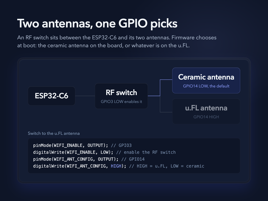
The XIAO ESP32C6 carries both an onboard ceramic antenna and a U.FL connector, and which one is live is decided by your firmware through an RF switch. Per Seeed's wiki: pull GPIO3 low to enable the RF switch control, then GPIO14 low selects the built-in antenna (the default) and GPIO14 high selects the external U.FL antenna. That makes range a software decision: prototype on the ceramic antenna, and if the device…
The XIAO ESP32C6 carries both an onboard ceramic antenna and a U.FL connector, and which one is live is decided by your firmware through an RF switch. Per Seeed's wiki: pull GPIO3 low to enable the RF switch control, then GPIO14 low selects the built-in antenna (the default) and GPIO14 high selects the external U.FL antenna.
That makes range a software decision: prototype on the ceramic antenna, and if the device ends up in a metal enclosure or far from the access point, solder nothing - just attach an antenna and flip two GPIOs at boot.
If range is disappointing, check you actually selected the antenna that's connected - transmitting on the U.FL setting with no antenna attached gives the worst of both worlds.
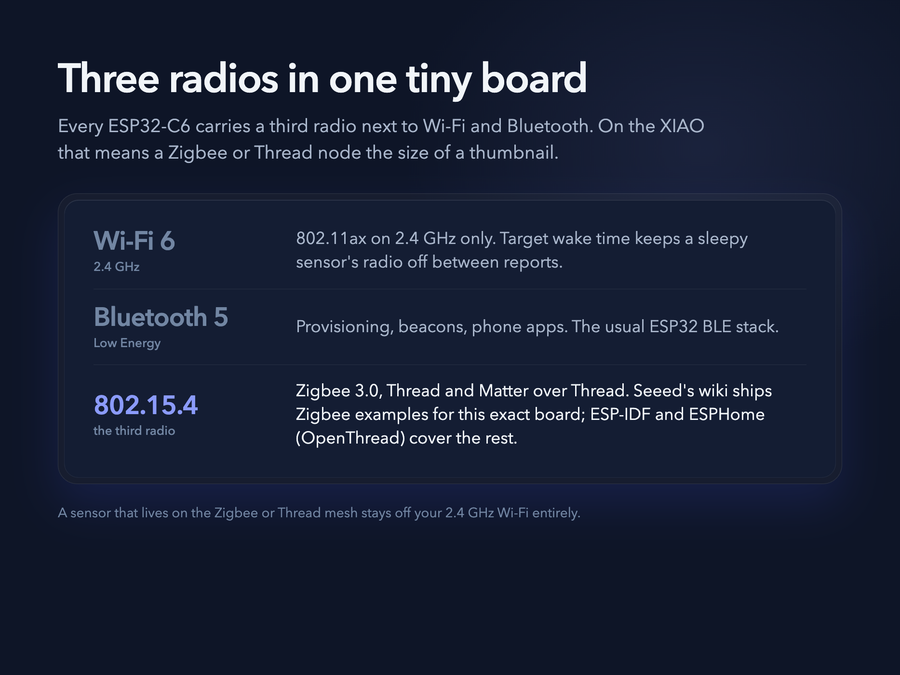
Like every ESP32-C6, this board has a third radio beyond WiFi 6 and Bluetooth 5 LE: an IEEE 802.15.4 radio for Zigbee 3.0, Thread, and Matter-over-Thread. Seeed's wiki ships worked Zigbee examples for this exact board, and the general C6 toolchain applies - Arduino via the ESP32 core, ESP-IDF Zigbee/Thread SDKs, and ESPHome with OpenThread support. Combined with the battery circuit below, this is a natural…
Like every ESP32-C6, this board has a third radio beyond WiFi 6 and Bluetooth 5 LE: an IEEE 802.15.4 radio for Zigbee 3.0, Thread, and Matter-over-Thread. Seeed's wiki ships worked Zigbee examples for this exact board, and the general C6 toolchain applies - Arduino via the ESP32 core, ESP-IDF Zigbee/Thread SDKs, and ESPHome with OpenThread support.
Combined with the battery circuit below, this is a natural board for Zigbee/Thread sensors that live on the mesh instead of crowding your 2.4 GHz WiFi.
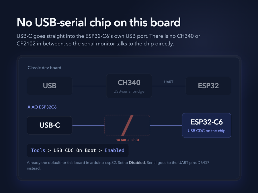
Like the SuperMini-class boards, the XIAO C6 has no USB-to-serial converter chip - USB-C connects straight to the ESP32-C6's native USB. Two everyday consequences: Serial output: keep Tools → USB CDC On Boot at "Enabled" (arduino-esp32's default for this board), or Serial.print() goes to the UART pins (D6/D7) instead of your serial monitor. Flashing: if the COM port never appears or an upload fails, hold BOOT while…
Like the SuperMini-class boards, the XIAO C6 has no USB-to-serial converter chip - USB-C connects straight to the ESP32-C6's native USB. Two everyday consequences:
- Serial output: keep Tools → USB CDC On Boot at "Enabled" (arduino-esp32's default for this board), or
Serial.print()goes to the UART pins (D6/D7) instead of your serial monitor. - Flashing: if the COM port never appears or an upload fails, hold BOOT while plugging in USB (or while tapping RESET) to force the ROM bootloader, then press RESET after flashing.
A crashed or deep-sleeping sketch takes the USB port down with it - normal for native-USB boards, not a broken board. The BOOT-button trick always recovers it.
Specifications
ESP32-C6 · 21 × 17.8 mm · vs other ESP32 chips →About this board
At 21 × 17.8 mm it's the smallest ESP32-C6 board we've measured.
At its core is the ESP32-C6 - a RISC-V part adding Wi-Fi 6 plus Thread/Zigbee radios.
Expect to pay about $5.20 - less than the ~$10 most ESP32-C6 boards go for.
The small footprint costs pins: 11 GPIO are broken out, versus 20 or so on a full-size board.
Onboard you'll find Zigbee, battery charging via Solder pads, status LEDs (User, Charge) and Reset/Boot buttons.
It flashes over native USB - no serial-converter driver needed, which isn't a given among ESP32-C6 boards.
The XIAO ESP32C6 is Seeed Studio's take on the ESP32-C6: a thumbnail-sized (21 x 17.8 mm) board with the C6's full radio set - WiFi 6, Bluetooth 5 LE, and an 802.15.4 radio for Zigbee, Thread, and Matter-over-Thread. Unlike the generic C6 boards in this class, it's a documented, branded product with a thorough wiki behind it.
Two hardware touches set it apart. First, a dual-antenna design: an onboard ceramic antenna plus a U.FL connector, selected at runtime by an RF switch on GPIO14. Second, real battery support: solder pads for a 3.7 V lithium cell with an onboard charging circuit and a charge-status LED.
The chip pairs a 160 MHz RISC-V core with a 20 MHz low-power core, 512 KB SRAM, and 4 MB flash (no PSRAM). Programming runs over USB-C through the C6's native USB - there's no separate serial chip. Seeed also sells a pre-soldered variant with the headers already fitted.
- Supports WiFi 6, Bluetooth 5, and Zigbee
- Ultra-small size (21x17.8 mm)
- Low power consumption with deep sleep support
- Dual antenna - onboard ceramic plus external u.FL, selected via RF switch on GPIO14 (enable with GPIO3 low)
Where to buy
prices are typical street pricesResources
Similar boards


