
KY-029 Dual Color LED Module
The KY-029 is a dual-color LED module featuring a 3mm LED that emits red and green light. By adjusting the intensity of each color using PWM, various color combinations can be achieved. The module's common cathode design simplifies integration with microcontrollers for visual indicators in projects.

KY-029 pinout
The KY-029 is a 3-pin two-color LED module (red/green, 3mm):
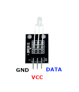
| Pin | Type | Description | Notes |
|---|---|---|---|
| Pin S (Signal) | Communication | LED anode (red or green) | PWM control for color selection |
| Pin middle (VCC) | Power | Common cathode (ground) | Connect to GND |
| Pin - (GND) | Power | Not connected | Leave unconnected (NC) |
Interface: PWM control for color intensity
Colors: Red, green, and mixed colors via PWM
Configuration: Common cathode (middle pin is GND)
Current: 20mA typical per LED
Resistor: Current-limiting resistor recommended
Applications: Status indicators, visual feedback, dual-state displays
Wiring the KY-029 to ESP32
To interface the KY-029 with an ESP32 for two-color LED control:
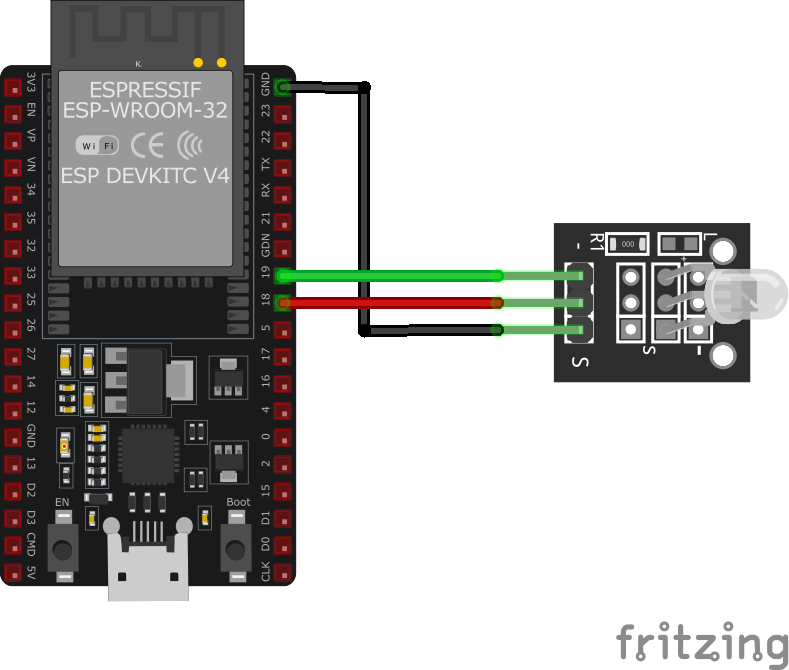
| KY-029 pin | ESP32 pin | Purpose |
|---|---|---|
| Pin S (Signal) | GPIO16 | LED control (via current-limiting resistor) |
| Pin middle (VCC) | GND | Common ground |
| Pin - (GND) | N/C | Not connected · optional |
Current-Limiting Resistor: Use ~220Ω resistor for LED protection
PWM Control: Use PWM for color mixing and brightness control
GPIO Selection: Use any PWM-capable GPIO, GPIO16 is just an example
3.3V Logic: ESP32’s 3.3V output sufficient with proper resistor
KY-029 code examples
int led_red = 16;   // Pin for red (GPIO16, matches the wiring above)
int led_green = 17; // Pin for green (GPIO17)

void setup() {
    // Initialization of output pins for the LEDs
    pinMode(led_red, OUTPUT);
    pinMode(led_green, OUTPUT);
}

void loop() {
    digitalWrite(led_red, HIGH);  // Red LED is switched on
    digitalWrite(led_green, LOW); // Green LED is switched off
    delay(3000);                  // Wait for 3 seconds

    digitalWrite(led_red, LOW);   // Red LED is switched off
    digitalWrite(led_green, HIGH); // Green LED is switched on
    delay(3000);                  // Wait for another 3 seconds
}
This Arduino code alternates between turning on the red and green LEDs every 3 seconds. Pins 11 and 10 are configured as outputs for the red and green LEDs, respectively.
#include <stdio.h>
#include "freertos/FreeRTOS.h"
#include "freertos/task.h"
#include "driver/ledc.h"
#include "driver/gpio.h"

#define LED_RED_PIN GPIO_NUM_16
#define LED_GREEN_PIN GPIO_NUM_17
#define LEDC_TIMER LEDC_TIMER_0
#define LEDC_MODE LEDC_LOW_SPEED_MODE
#define LEDC_CHANNEL_RED LEDC_CHANNEL_0
#define LEDC_CHANNEL_GREEN LEDC_CHANNEL_1
#define LEDC_DUTY_RES LEDC_TIMER_8_BIT
#define LEDC_FREQUENCY 5000

void app_main(void) {
    // Configure timer for LEDC
    ledc_timer_config_t ledc_timer = {
        .speed_mode = LEDC_MODE,
        .duty_resolution = LEDC_DUTY_RES,
        .timer_num = LEDC_TIMER,
        .freq_hz = LEDC_FREQUENCY,
        .clk_cfg = LEDC_AUTO_CLK
    };
    ledc_timer_config(&ledc_timer);

    // Configure LEDC channel for red LED
    ledc_channel_config_t ledc_channel_red = {
        .speed_mode = LEDC_MODE,
        .channel = LEDC_CHANNEL_RED,
        .timer_sel = LEDC_TIMER,
        .intr_type = LEDC_INTR_DISABLE,
        .gpio_num = LED_RED_PIN,
        .duty = 0,
        .hpoint = 0
    };
    ledc_channel_config(&ledc_channel_red);

    // Configure LEDC channel for green LED
    ledc_channel_config_t ledc_channel_green = {
        .speed_mode = LEDC_MODE,
        .channel = LEDC_CHANNEL_GREEN,
        .timer_sel = LEDC_TIMER,
        .intr_type = LEDC_INTR_DISABLE,
        .gpio_num = LED_GREEN_PIN,
        .duty = 0,
        .hpoint = 0
    };
    ledc_channel_config(&ledc_channel_green);

    while (1) {
        printf("Red LED ON\n");
        ledc_set_duty(LEDC_MODE, LEDC_CHANNEL_RED, 255);
        ledc_update_duty(LEDC_MODE, LEDC_CHANNEL_RED);
        ledc_set_duty(LEDC_MODE, LEDC_CHANNEL_GREEN, 0);
        ledc_update_duty(LEDC_MODE, LEDC_CHANNEL_GREEN);
        vTaskDelay(pdMS_TO_TICKS(3000));

        printf("Green LED ON\n");
        ledc_set_duty(LEDC_MODE, LEDC_CHANNEL_RED, 0);
        ledc_update_duty(LEDC_MODE, LEDC_CHANNEL_RED);
        ledc_set_duty(LEDC_MODE, LEDC_CHANNEL_GREEN, 255);
        ledc_update_duty(LEDC_MODE, LEDC_CHANNEL_GREEN);
        vTaskDelay(pdMS_TO_TICKS(3000));
    }
}
This ESP-IDF code configures GPIO16 and GPIO17 as PWM outputs using the LEDC peripheral. It alternates between turning on the red and green LEDs every 3 seconds, simulating a simple traffic light effect.
output:
  - platform: gpio
    pin: GPIO16
    id: led_red
  - platform: gpio
    pin: GPIO17
    id: led_green

light:
  - platform: binary
    name: "KY-029 Red LED"
    output: led_red
  - platform: binary
    name: "KY-029 Green LED"
    output: led_green
Each LED leg is a plain GPIO output (GPIO16/GPIO17 per the wiring above) exposed as a separate binary light - the KY-029's two dies are just on/off LEDs. Use ledc outputs with monochromatic lights instead if you want dimming.
[env:esp32dev]
platform = espressif32
board = esp32dev
framework = arduino
monitor_speed = 115200#include <Arduino.h>
int led_red = 16; // Pin for red (GPIO16, matches the wiring above)
int led_green = 17; // Pin for green (GPIO17)
void setup() {
// Initialization of output pins for the LEDs
pinMode(led_red, OUTPUT);
pinMode(led_green, OUTPUT);
}
void loop() {
digitalWrite(led_red, HIGH); // Red LED is switched on
digitalWrite(led_green, LOW); // Green LED is switched off
delay(3000); // Wait for 3 seconds
digitalWrite(led_red, LOW); // Red LED is switched off
digitalWrite(led_green, HIGH); // Green LED is switched on
delay(3000); // Wait for another 3 seconds
}This PlatformIO code alternates between turning on the red and green LEDs every 3 seconds, with messages printed to the serial monitor.
import machine
import time

LED_RED_PIN = machine.Pin(16, machine.Pin.OUT)
LED_GREEN_PIN = machine.Pin(17, machine.Pin.OUT)

while True:
    LED_RED_PIN.on()
    LED_GREEN_PIN.off()
    print("Red LED ON")
    time.sleep(3)

    LED_RED_PIN.off()
    LED_GREEN_PIN.on()
    print("Green LED ON")
    time.sleep(3)
This MicroPython script toggles the KY-029 red and green LEDs every 3 seconds using GPIO16 and GPIO17.
KY-029 specifications
About the KY-029
The KY-029 is the KY-011’s smaller sibling: the same red and green dies in one common-cathode package, just in a 3mm case instead of 5mm, with no blue channel and no controller on board. Electrically the two modules behave identically - mixing red and green with PWM still only reaches yellow and orange, never a true RGB spectrum, since there’s no blue die to complete it.
Like the KY-011, the KY-029 carries no current-limiting resistor of its own, so each LED leg needs one added externally - around 120 ohm at 3.3V or 220 ohm at 5V keeps both dies under their 20 mA rated forward current. Wire the shared cathode to GND and drive the red and green legs independently through PWM-capable GPIOs; the smaller 3mm package is really just a form-factor choice for tighter enclosures; and a straight digitalWrite() HIGH is enough if color mixing isn’t needed, since that just gives full brightness on whichever channel is set.
KY-029 troubleshooting
LED Not Lighting Up
›
Issue: The LED does not emit any light.
Solutions:
- Ensure proper wiring connections between the module and the microcontroller.
- Verify that the microcontroller's GPIO pins are correctly configured as outputs.
- Check if appropriate current-limiting resistors are used to prevent LED damage.
Incorrect Color Display
›
Issue: The LED displays unexpected colors or brightness levels.
Solutions:
- Confirm that the PWM signals are correctly configured for both red and green LEDs.
- Ensure that the common cathode is properly connected to ground.
- Check for any short circuits or loose connections on the module.
Where to buy the KY-029

Resources
Similar sensors


